DeFelsko PosiTest-AT Pull Off Adhesion Tester Web Manual

In accordance with ASTM D4541, D7234, ISO 4624 and others, the PosiTest AT evaluates the adhesion (pull-off strength) of a coating by determining the greatest tensile pull-off force that it can bear before detaching. Breaking points, demonstrated by fractured surfaces, occur along the weakest plane within the system consisting of the dolly (loading fixture, stub), glue, coating layers and substrate.
PosiTest AT Kit Contents
|
|
![]()
Basic Steps to Perform a Pull-Off Test![]()
- Dolly & Coating Preparation
The dolly and the coating are cleaned and abraded. - Glue & Dolly Application
The glue is prepared and applied to the dolly. The dolly is is then adhered to the coated surface and the glue is allowed to cure. - Test Area Separation - optional
- Pull-Off Test
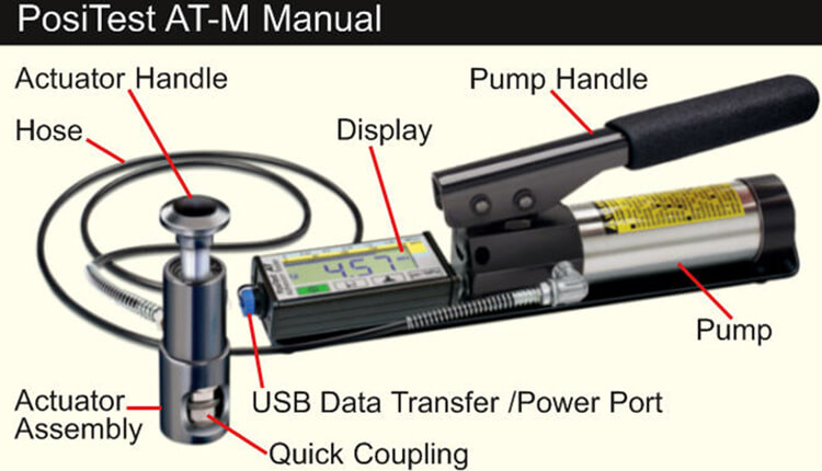
- PosiTest AT-M (manual)
- PosiTest AT-A (automatic)
- Analysis of Test Results
Dolly Preparation
- To remove oxidation and contaminants, place the included abrasive pad on a flat surface and rub the base of the dolly across the pad 4-5 times.
- As required, remove residue left from the abrading process using a dry cloth or paper towel.
Coating Preparation
- Lightly roughen the coating using the included abrasive pad.
NOTE: As coating abrasion may introduce flaws, it should only be used when necessary to remove surface contaminants, or when the bond strength between the glue and the coating is insufficient for pull testing. - To promote the bond between the dolly and the coating, degrease the area of the coating to be tested using alcohol or acetone to remove any oil, moisture or dust.
NOTE:Ensure that any alternative abrasion techniques, degreasers or adhesives do not alter the properties of the coating. Test by applying a small amount of degreaser or glue to a sample area and observing effects.
Glue Selection
The glue included in the PosiTest Adhesion Tester kit has been selected due to its versatility. This glue has minimal impact on a variety of coatings and has a tensile strength exceeding the maximum performance capabilities of the pressure system under ideal conditions. Other glues may be preferred based on requirements such as cure time, coating type, working temperature and pull-off strength. Quick curing one-part cyanoacrylates (super glues) may be sufficient for painted surfaces, but two-part epoxies are preferred for porous or rough coatings.
Dolly Application
- Mix the glue per manufacturer’s instructions and apply a uniform film of glue on the base of the dolly.
- Attach the dolly to the prepared coating test area.
NOTE: If the coated surface to be tested is overhead or vertical, a means to hold the dolly in place during the cure time may be required, i.e. removable tape. - Gently push down on the dolly to squeeze out excess adhesive. Do not twist or slide the dolly back and forth on the coating as air bubbles may be generated.
- Carefully remove excess adhesive from around the edges of the dolly with included cotton swabs.
- Allow to cure per the adhesive manufacturer's instructions.
The decision of when to cut around a dolly is dependent on the standard, specification or contractual agreement to which the test is to comply. The primary purpose for cutting through the coating is to isolate a specific diameter test area. When the decision to cut into the coating has been made, it is recommended to cut all the way through to the substrate. As a minimum, it is suggested to carefully cut away excess glue from the dolly application process. This typically prevents a larger area of coating from being pulled away from the substrate, resulting in a higher pull-off pressure.
Cutting Instruction
- Cut through the coating around the edges of the dolly with the included cutting tool, removing any excess glue.
- Clear away any debris from the cutting process.
NOTES:
- Cutting may induce coating surface flaws such as microcracking that may alter test results.
- For coatings with strong lateral bonding, it is recommended to cut completely through the coating down to the substrate.
When testing very thick coatings, an optional drilling template may be preferred.
| Upon completion of the pull-off test, the dolly and coated surface should be examined. In addition to pull-off force, many National and International standards such as ASTM D4541 and ISO?4624 require the nature of the fracture to be recorded. |  |
- Cohesive fracture: fracture occurs within a coating layer (same coating on dolly face and coated surface).
- Adhesive fracture: fracture occurs at the interface between layers (coating on dolly face differs from surface).
- Glue failure: visible separation of the glue from itself, the coating or dolly (no coating visible on the dolly face).
| Glue failures typically occur when the glue is improperly mixed or the coated surface has not been adequately prepared (see Glue & Dolly Application). | 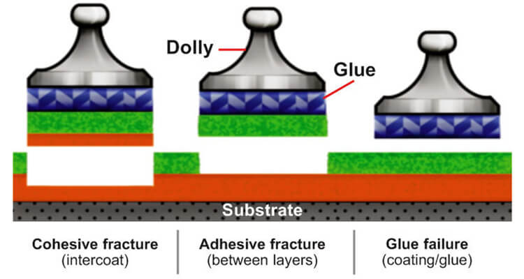 |
The PosiTest AT-A model provides an interface to document the nature of the fracture for each pull-off test (see Recording Fracture Analysis). Fracture results are included in test reports.
| The PosiTest AT-M powers-up and displays dashes when the |
 |
Quick Guide
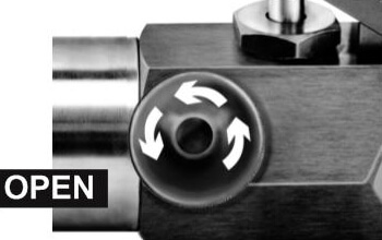
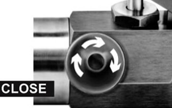
- Open pressure relief valve completely (turn counter clockwise)
- Connect the actuator to the dolly
- Close the pressure relief valve completely (turn clockwise)
- Zero - Press the
 button
 - Pump pressure into the system until the dolly pulls
|
 |
- Push the actuator handle completely down into the actuator assembly. Place the actuator over the dolly head and attach the quick coupling to the dolly by reaching through the holes in the actuator and lifting the coupling. Release the quick coupling when the dolly head is completely engaged.
|
 |
As required, verify and adjust the![]() dolly size by pressing the button. Select the pressure units by pressing the
dolly size by pressing the button. Select the pressure units by pressing the![]() button. The instrument will maintain these settings even after the button is pressed.
button. The instrument will maintain these settings even after the button is pressed.
- Zero the instrument BEFORE pumping by pressing thebutton. This prepares the instrument for the test by clearing the display, and zeroing the instrument.
- Prime the pump slowly until the displayed reading approaches the priming pressure. The priming pressure is the point that the instrument begins calculating and displaying the pull rate. It is also the pressure at which the ability to store readings is enabled.
Priming pressures for the various dolly diameters are: For optimum results, prior to exceeding the priming pressure, return the pump handle to its full upright position and then complete a single continuous stroke at the desired pull rate until the actuator separates the dolly from the coating.
| 10 mm | 400 psi | 2.8 MPa |
| 14 mm | 200 psi | 1.4 MPa |
| 20 mm | 100 psi | 0.7 MPa (default settings) |
| 50 mm | 50 psi | 0.4 MPa |
- Open the pressure relief valve and remove the dolly from the actuator assembly.
- Readings may be stored into memory by pressing thebutton (memory storage for up to 200 pulls). Press again to review stored readings. Stored measurements can be accessed using our PosiSoft 3.0 desktop software (see Accessing Stored Measurement Data).
To remove all stored test results from memory, press and hold the![]() button, then press the
button, then press the![]() button. The
button. The![]() icon will disappear from the display.
icon will disappear from the display.
The PosiTest AT-A powers-up when the![]() button is pressed. ?To preserve battery life, the instrument powers-down after 5 minutes of no activity. Alternatively, press and hold the
button is pressed. ?To preserve battery life, the instrument powers-down after 5 minutes of no activity. Alternatively, press and hold the![]() button for 5 seconds or select Power Off from the menu. Instrument functions are menu controlled. To access the Menu, press the
button for 5 seconds or select Power Off from the menu. Instrument functions are menu controlled. To access the Menu, press the![]() button. Navigate using the multifunction keypad or touch screen display.
button. Navigate using the multifunction keypad or touch screen display.
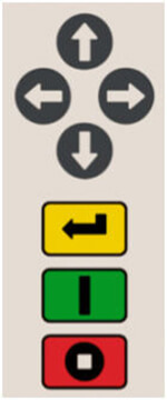
- Access Menu / Select
- Power On / Start Test / Return to Main View
- Stop Test / Power-down (hold for 5 seconds)
Screen Capture
Press both buttons ![]()
![]() at any time to copy and save an image copy of the the current display. The last 10 screen captures are stored in memory and can be accessed when connected to a computer (see PosiSoft USB Drive).
at any time to copy and save an image copy of the the current display. The last 10 screen captures are stored in memory and can be accessed when connected to a computer (see PosiSoft USB Drive).
Touch Screen Display
Use the touch screen to interact with menu options. Swipe horizontally to navigate between views or vertically to move between batch readings. Alternatively, the directional buttons can be used for navigation. |
 |
- Push the actuator handle completely down into the actuator assembly. Place the actuator over the dolly head and attach the quick coupling to the dolly by reaching through the holes in the actuator and lifting the coupling. Release the quick coupling when the dolly head is completely engaged.
- Press the button to power-up the instrument if necessary.
- Verify Pull Parameters are set to the preferred dolly size, pull rate, pull limit and hold time. Change if necessary.
- NOTE: If recording of test results is desired, a memory batch must be opened prior to the test. ?Select New Batch from the Memory menu.
- Press thebutton to initiate the test.
- The instrument begins building pressure (priming stage) and a green animated arrow (up) appears on the display. When the priming pressure is achieved the LCD starts displaying pressure over time on the pull chart. Refer to Step 5 for Priming Pressures.
- Pressure build-up stops when the dolly is pulled from the surface, the pull limit has been reached or whenthe button is pressed. The maximum pressure value will blink on the display and a red animated arrow (down) will display while the pump retracts the actuator.
CAUTION: To avoid injury, keep fingers away from the quick coupling and actuator assembly until the pull test has completed and the actuator has been fully retracted. Press the stop button to abort the pull test at any time.
NOTE: Setting a Pull Limit or stopping the test before a fracture occurs is useful when the coating strength exceeds specified requirements.
- Remove the dolly from the actuator assembly.
- Examine the dolly and surface to analyze the result.
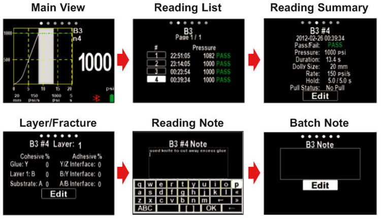
If a memory batch is open, the maximum pressure result is automatically stored into Memory. Pass/fail, pull parameters, date and time are also recorded.
The nature of the fracture (cohesive, adhesive, glue), batch and reading notes can also be recorded. Swipe the touch screen horizontally or use the left/right buttons to navigate to the appropriate view and select Edit. See Memory Views.
All stored measurement data can be accessed using PosiSoft solutions (see Accessing Stored Measurement Data).
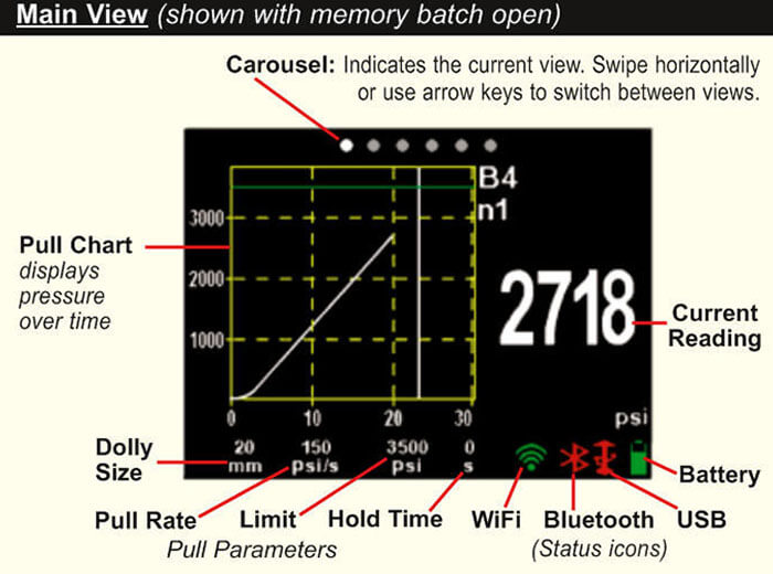
When a memory batch is Open, a carousel appears at the top of the display. Views are represented by dots, the solid dot indicates the current view.
Swipe horizontally to navigate between views or vertically to move between batch readings. Alternatively, the directional buttons can be used for navigation.
Use the touch screen to interact with menu options. Swipe horizontally to navigate between views or vertically to move between batch readings. Alternatively, the directional buttons can be used for navigation. |
 |
The cohesive and adhesive fracture visual analysis can be recorded using the PosiTest AT-A's keypad or touch screen display. Alternatively, the information can be reported post test using the PosiTector App.
Fractures are visually estimated and recorded as a percent of each. The two layer example below illustrates a cohesive fracture within coating layer 1 and layer 2 (visually estimated at 50% each). Recorded results are included in reports. |
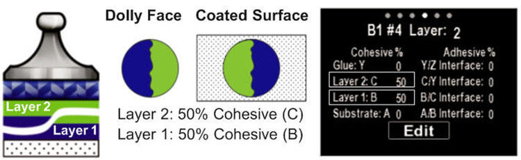 |
The PosiTest AT-A can record fracture information for up to five layers. Cohesive and adhesive fractures are identified as follows: |
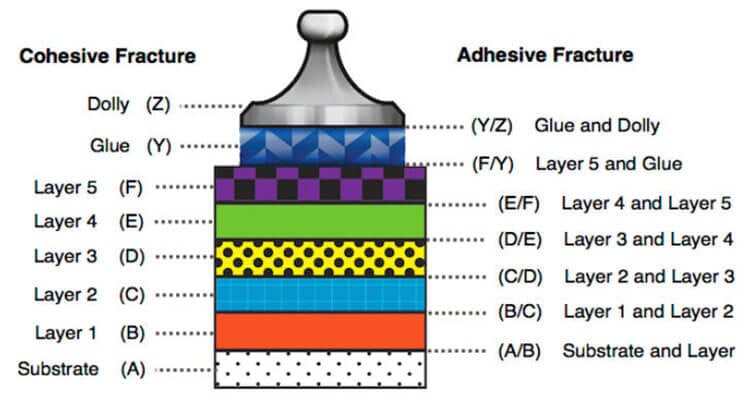 |
Select Edit to set the number of layers and cohesive/adhesive fracture details. Use the |
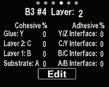 |
Examples:
100% cohesive fracture at D/E coating interface (layer 3/layer 4) |
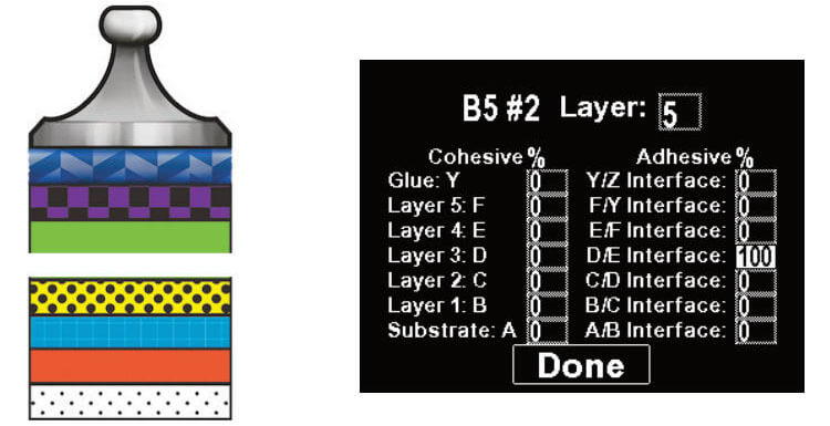 |
|
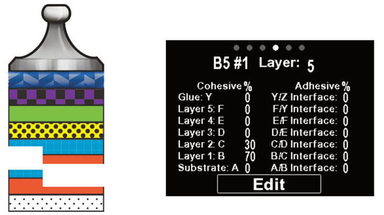
70% cohesive failure within layer 1; 30% cohesive within layer 2
|
 |
The PosiTest AT-A stores 100,000 readings in up to 1,000 batches. Stored measurements can be reviewed on-screen or accessed via computers, tablets and smart phones.
New Batch
Closes any currently opened batch and creates a new memory batch, named using the lowest available number (example:?B2). New batches are date stamped when they are created.
Open
Selects a previously created batch to open and make current.
Close
Stops the recording process, closes the current batch, and removes batch information from the display.
Delete
Removes a batch and associated measurements from memory.
Select desired parameter using the ![]()
![]() buttons or touch screen. Use the
buttons or touch screen. Use the ![]() and
and ![]() buttons to adjust.
buttons to adjust.
- Dolly Size: Select the dolly size being utilized for the test (10, 14, 20 or 50 mm)
- Rate: User selectable pull rate (unit/sec). Specified rate is maintained for the duration of the test.
- Limit: Pressure will build-up until the set Limit is reached or the dolly is pulled from the surface, whichever occurs first. By default, the instrument will pull to maximum for selected dolly size (see Technical Specifications).
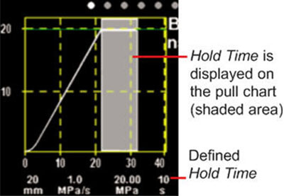
Hold Time: (up to 60 seconds) pressure is maintained (held) at defined Limit. Default: 0 seconds.
|
 |
Orientation
Rotates display between landscape (default) or portrait views. Ideal for use in horizontal or vertical positions.
Units
Converts the display from psi, MPa, N/mm2 or Newtons (unit of force). Existing measurements in memory are not converted. Switching units closes Memory.
Displays the model number & serial number, PosiSoft.net registration key, the amount of remaining memory for storage of readings, date and time, and software packages.
For security purposes, the registration key is required to add the Gage to your PosiSoft.net account (see Accessing Stored Measurement Data).
Restores factory settings and returns the instrument to a known condition. The following occurs:
- All batches, stored readings, notes, batch names and screen captures are erased.
- Menu settings are returned to the following:
| Memory = OFF | Bluetooth = ON | Units = psi |
| Pull Parameters = default | WiFi = ON | Backlight = Sun |
| Orientation = Landscape | USB Drive = ON | Language = English |
NOTE: Date, Time and WiFi are not affected by a Reset
Allows connection to your local wireless network or mobile hot spot. Ideal for using your network's internet connection for synchronizing stored measurements with PosiSoft.net. See www.defelsko.com/wifi |
 |
Enable ![]()
Turns WiFi functionality ON. When selected, the ![]() icon will appear on the display. To deactivate WiFi, uncheck the Enable box.
icon will appear on the display. To deactivate WiFi, uncheck the Enable box.
Connect your smart device/computer to a PosiTector Advanced body wirelessly without the need for a separate network. Wirelessly import readings into PosiSoft Desktop v4.0 Software whenever a WiFi network is not available or out-of-range.
To enable, select Access Point from the Connect > WiFi menu. The Access Point icon ![]() will display in the upper left of the PosiTector display.
will display in the upper left of the PosiTector display.
Securing your Access Point -
To ensure the PosiTector is only accessible to authorized devices, it is important that you enter a passphrase (password) for the Access Point. The default Passphrase is password.
In the Connect > WiFi > Setup menu, select AP Passphrase.
Press ![]() button to display on-screen keyboard. Enter a Passphrase for the Access Point. The Passphrase will be required for all devices connecting to the PosiTector's Access Point.
button to display on-screen keyboard. Enter a Passphrase for the Access Point. The Passphrase will be required for all devices connecting to the PosiTector's Access Point.
The PosiTector is now visible to all WiFi enabled devices. Simply connect your devices WiFi to the new PosiTector Access Point. All PosiTectors are uniquely identified by their respective gage body serial numbers.
AP Channel - Default Channel: 6
For most users the default channel will not have to be altered. If you are experiencing poor connection or are unable to connect, try another channel.
In the Connect > WiFi > Setup menu, select AP Channel
Press the UP center navigation button to highlight the channel. Use the (-) or (+) buttons to change the channel. Press the DOWN navigation button and select OK. Press ![]() the button.
the button.
Networks: With WiFi Enabled the Gage will allow the user to add a new network and will automatically check for available local networks. Available networks detected by the Gage are listed on the screen along with any networks that the Gage has previously been connected to that are not currently within connection range.
Information: Gage displays information about the local WiFi network connection including.
- SSID: the network's name
- State: displays if the Gage is connected to the network or not
- IP Address: the network's IP Address
- Setup: Allows user to setup a WiFi connection
- IP Settings: enter the IP information as follows.
- IP Type (DHCP or Statis), IP Address,
- Gateway, Netmask, DNS1, DNS2
- Server Enable: enables a connection between the network and the Gage
- Gage Name: enter a name for the Gage (up to 14 characters)
- AP Channel: The access point channel corresponding to a frequency range. (Default Channel: 6)
- AP Passphrase: A series of characters, numbers or symbols used to log on to a WiFi network. (Default Passphrase: password)
- WiFi Reset: erases all WiFi settings
When USB Drive is checked ![]() , the PosiTector gage uses a USB mass storage device class which provides users with a simple interface to retrieve stored data in a manner similar to USB flash drives, digital cameras and digital audio players.
, the PosiTector gage uses a USB mass storage device class which provides users with a simple interface to retrieve stored data in a manner similar to USB flash drives, digital cameras and digital audio players.
USB Drive is also required to import stored measurements into PosiSoft Desktop software (pg.24). Once connected, any computer can view measurements stored in memory by navigating a virtual drive labeled "PosiTector” using the included USB cable.
A formatted HTML report is viewed by selecting the "index.html" or “START_HERE.html” file found in the root directory. Optionally, text ".txt" files located in each batch folder provide access to measurement values. Stored datasets and graphs can be viewed or copied using universal PC/Mac web browsers or file explorers.
When your PosiTector is first connected to your Windows PC via a USB cable, an enumeration process is started that installs device drivers without re-booting your computer. You may see several pop-up windows in the taskbar at the bottom right of your screen. Wait for the entire process to be completed before proceeding.
Serial Streaming via USB (Advanced models only, serial numbers 784000 and greater)
Advanced gage bodies have the ability to serial stream live readings from the USB port.
The following document links will help operators use this feature:
PosiTector Advanced USB Serial Streaming Instructions
Retrieving stored screen captures:
The last 10 screen captures stored in memory can be accessed by navigating to the "screen capture" directory within the "PosiTector" virtual drive.
- NOTE: When connected, power is supplied through the USB cable. The batteries are not sed and the body will not automatically power down. If rechargeable (NiMH) batteries are installed, the instrument will trickle charge the batteries.
The below WiFi, USB and Bluetooth menus contain a Sync .net Now option. When selected, the Gage immediately synchronizes stored measurement data via its respective communication method (internet connection required).
Alternatively, select Auto Sync .net from within the USB connect menu to automatically synchronize upon connection to a PC. Additional measurements added to memory while connected are synchronized only when the USB cable is disconnected and reconnected, or when the Sync .net Now option is selected.
WiFi connected gages automatically attempt synchronization upon power-up.
NOTE: PosiSoft Desktop is required when using USB or Bluetooth connections to synchronize measurements with PosiSoft.net.
(Advanced models only, serial numbers 784000 and greater) |
When Enabled ![]() , allows communication with a smart device running the PosiTector App via auto-pairing Bluetooth Smart (BLE) wireless technology.
, allows communication with a smart device running the PosiTector App via auto-pairing Bluetooth Smart (BLE) wireless technology.
Select ![]() batches to flag them for synchronization to the PosiTector App. New batches created while Bluetooth Smart is enabled are automatically selected.
batches to flag them for synchronization to the PosiTector App. New batches created while Bluetooth Smart is enabled are automatically selected.
Sync Batches
With Bluetooth Smart enabled, select Sync Batches to transfer selected ![]() batches to the PosiTector App. This is useful when switching between smart devices, as only readings and batches that have yet to be synchronized with any smart device are synchronized automatically.
batches to the PosiTector App. This is useful when switching between smart devices, as only readings and batches that have yet to be synchronized with any smart device are synchronized automatically.
NOTE: If Bluetooth Smart is disabled, data from batches selected in the Sync Batches menu are held in a queue until communication with the PosiTector App is re-established.
Send Batches
Transfers selected ![]() batches to the PosiTector App (useful when switching between devices).
batches to the PosiTector App (useful when switching between devices).
The Send Batches option is visible in the Bluetooth Smart menu when the Gage is connected to a smart device running the PosiTector App.
Allows individual readings to be sent to a computer, printer or compatible device as they are taken using Bluetooth wireless technology. See www.defelsko.com/bluetooth |
Pairing
The instrument and receiving device must be paired before stored or streamed datasets can be transmitted. For pairing instructions, see http://www.defelsko.com/bluetooth
Info
Lists information about your current Bluetooth connection, including the currently paired device and MAC address..
Stream
When checked, the instrument will stream datasets to the paired Bluetooth Device as they are taken. Datasets can be streamed as they are taken to the optional Bluetooth printer or third-party computer software.
Powder Probes
Displays menu options that enable the PosiTector body to communicate with wireless PosiTector PC probes. See http://www.defelsko.com/pc
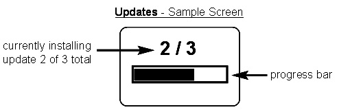
Determine if a software update is available for your Gage. See www.defelsko.com/update
To perform an update the Gage must be connected to an internet connected PC with PosiSoft Desktop or WiFi network. |
 |
WARNING: Ensure that stored measurements are backed up to a PC or PosiSoft.net.
The Gage will perform a Hard Reset after an update. All stored measurements will be erased from memory.
![]() Do Not unplug the Gage during the update operation.
Do Not unplug the Gage during the update operation.
![]() Power Supply / Battery Indicator
Power Supply / Battery Indicator ![]()
Power Source: 3 AAA alkaline, Lithium or optional Nickel-metal hydride (NiMH) rechargeable batteries. For best battery indicator results, ensure the appropriate Battery Type is selected in the Setup > Battery Type menu.
The battery indicator ![]() displays a full bar with fresh alkaline or fully charged batteries installed. As the batteries weaken, the bar will be reduced. When the battery symbol is low
displays a full bar with fresh alkaline or fully charged batteries installed. As the batteries weaken, the bar will be reduced. When the battery symbol is low ![]() the Gage can still be used, but the batteries should be changed or recharged at the earliest opportunity. The Gage will turn off automatically when batteries are very low, preceded by a Low Battery Warning on the display.
the Gage can still be used, but the batteries should be changed or recharged at the earliest opportunity. The Gage will turn off automatically when batteries are very low, preceded by a Low Battery Warning on the display.
![]() To retain all user settings and stored memory readings, only replace the batteries after the instrument has powered-down. Battery performance decreases at low temperatures.
To retain all user settings and stored memory readings, only replace the batteries after the instrument has powered-down. Battery performance decreases at low temperatures.
Battery performance decreases at low temperatures
Calibration
The PosiTest AT is shipped with a Certificate of Calibration showing traceability to a national standard. For organizations with re-certification requirements, the PosiTest AT may be returned at regular intervals for calibration. DeFelsko recommends that our customers establish their instrument calibration intervals based upon their own experience and work environment. Based on our product knowledge, data and customer feedback, a one year calibration interval from either the date of calibration, date of purchase, or date of receipt is a typical starting point.
Verification
The PosiTest AT Verifier is available for verifying the accuracy and operation of PosiTest Adhesion Testers and is an important component in fulfilling both ISO and in-house quality control requirements. Fully portable with hardshell carry case for use in the field or laboratory.
Conforms to: ASTM D4541, ASTM D7234, ISO?4624 and others.
Specifications:
Resolution:? 1 psi (0.01 MPa)
Accuracy:?±1% Full Scale
| Dolly Size (mm) | Max Pull-Off Pressure (AT-M) | Max Pull-Off Pressure (AT-A) |
| 10 mm | 10,000 psi (70 MPa) | 14,000 psi (96 MPa) |
| 14 mm | 6,000 psi (40 MPa) | 7,000 psi (50 MPa) |
| 20 mm | 3,000 psi (20 MPa | 3,500 psi (24 MPa) |
| 50 mm* | 500 psi (3.5 MPa) | 560 psi (3.8 MPa) |
*requires the use of a 50 mm stand off
The instrument also measures in N/mm2 and Newtons (unit of force).
Before returning the instrument for service
- Install new batteries in the proper alignment as shown within battery compartment.
- Examine the surface temperature sensor for dirt or damage.
- If the humidity sensor is slow to respond or reading erratically, recondition the sensor by removing the probe from the gage body and wrapping it in a damp cloth overnight.
- Perform a Hard Reset.
- If issue is not resolved, Update your PosiTector gage body and re-attempt measurements.
![]() Limited Warranty, Sole Remedy and Limitied Liability
Limited Warranty, Sole Remedy and Limitied Liability![]()
DeFelsko's sole warranty, remedy, and liability are the express limited warranty, remedy, and limited liability that are set forth on its website:
www.defelsko.com/terms
© DeFelsko Corporation USA 2017
All Rights Reserved
This manual is copyrighted with all rights reserved and may not be reproduced or transmitted, in whole or part, by any means, without written permission from DeFelsko Corporation.
DeFelsko and PosiTector are trademarks of DeFelsko Corporation registered in the U.S. and in other countries. Other brand or product names are trademarks or registered trademarks of their respective holders.
Every effort has been made to ensure that the information in this manual is accurate. DeFelsko is not responsible for printing or clerical errors.