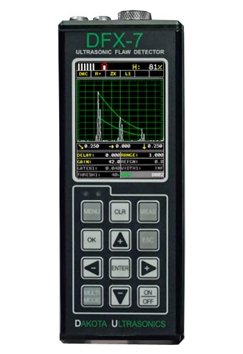
The TI-DFX7 Ultrasonic Flaw Detector uses the latest Color LCD Technology with super-fast re-fresh rate.
Features
| Flaw Detector Features | | TRIG | Trigonometric display of beam path, depth, surface distance, and curved surface correction. Used with angle beam transducers | | DAC | Up to 8 points may be entered and used to digitally draw a DAC curve. Reference -2, -6, -10, (-6/-12), (-6/-14), (-2/-6/-10) dB. Amplitude displayed in %DAC or dB | | AWS | Automatic defect sizing in accordance with AWS D1.1 structural welding code | | AVG/DGS | Automatic defect sizing using probe data. Stores up to 64 custom setups | | TCG | Time corrected gain. 50 dB dynamic range, 20 dB per microsecond, up to 8 points for curve definition | | Measurement Mode | Pulse-Echo (P-E) measures from 0.025 in to 100 ft. (0.63mm to 3048 cm) | | Auto-Cal | Provides automatic calibration with two reference points | | Detection Modes | Zero Crossing, Flank and Peak | | Display Freeze | Hold current waveform on screen | | Peak Memory | For echodynamic pattern determination | | | | Thickness Gauge Features | | Measurement Modes (Dual Element): | | Pulse-Echo Mode (P-E) | (Pit & Flaw Detection) measures from 0.025 in to 100 ft. (0.63mm to 3048 cm) | | Pulse-Echo Coating Mode (PECT) | (Material, Coating, Pit & Flaw Detection): Material: 0.025 in to 100 ft. (0.63mm to 3048 cm). Coating: 0.001 to 0.100 inches (0.01 to 2.54 millimeters) | | Pulse-Echo Temp Comp Mode (PETP) | (Pit & Flaw Detection) Auto temperature compensation – measures from 0.025 in to 100 ft. (0.63 mm to 3048 cm) | | Echo-Echo Mode (E-E) | (Thru Paint & Coatings) measures from 0.050 to 4.0 inches (1.27 to 102 millimeters). Will vary based on coating | | Echo-Echo Verify (E-EV) | (Thru Paint & Coatings) measures from 0.050 to 1.0 inches (1.27 to 25.4 millimeters). Will vary based on coating | | Coating Only Mode (CT) | (Coating Thickness) Measures from 0.0005 to 0.100 inches (0.0127 to 2.54 millimeters). Range will vary +/- depending on the coating | | One and two point calibration option for material & coating, or selection of basic material types. | | Auto probe zero, recognition and temperature compensation | | High speed scan up to 50 readings per second | | Audible alarm with hi/lo limits | | Built-in differential mode for QC inspections | | 64 custom setup configurations |
Specifications
| General | | Size | 2.5W x .5H x 1.24D in (63.5 x 165 x 31.5mm) | | Weight | 14 ounces (.397kgs), with batteries | | Case | Extruded aluminum body with nickel plated aluminum end caps (gasket sealed) | | Display | 1/4 VGA AMOLED color display (320 x 240 pixels). Viewable area 1.7 x 2.27 in (43.2 x 57.6 mm). 16 color pallete, multiple color options, and variable brightness | | Screen Refresh Rate | Selectable 60 or 120Hz | | Display Views | Flaw Detector: Full wave, +/- Rectified, or RF. Thickness Gauge: Digits, +/- Rectified, RF, or B-Scan | | Timing | Precision 25MHz TCXO with single shot 100 MHz 8 bit ultra low power digitizer | | Measurement Gates | Two independent gates (Flaw), and three gates (thickness). Start & width adjustable over full range. Amplitude 5-95%, 1% steps. Positive or negative triggering for each gate with audible and visual alarms | | Operating Temperature | 14 to 140F (-10C to 60C) | | Environmental | Meets IP65 requirements | | Warranty | 2 year limited | | | | Calibration | | Automatic Calibration | Longitudinal (straight), or Shear (angle) | | Probe Types | Single Contact, Dual, Delay, and Angle | | Units | English (in), Metric (mm), or Time (ìs) | | Velocity | 0.0100 to 0.6300 in/ìs (256–16,000 m/s) | | Test Range | 0 to 0.280in (7.11mm) minimum, to 1200in (30,480mm) maximum at steel velocity. Continuously variable | | Zero Offset (Probe Zero) | 0–999.999 ìs | | Material Velocity Table | Contains longitudinal and shear velocities for a variety of material types | | | | Pulser | | Pulser Type | Two adjustable square wave pulsers and receivers | | P.R.F. | 8 to 333Hz in selectable steps (8, 16, 32, 66, 125, 250, 333Hz) | | Pulser Voltage | 200 volt peak amplitude, rise/fall time < 10ns into 50ohm | | Pulse Width | 40 to 400 ns. Selectable step options (spike, thin or wide) | | | | Receiver | | Gain | 0 to 110dB with 0.2dB resolution. Manual and AGC control | | Damping | 50, 75, 100, 300, 600, & 1500 ohms | | Frequency Bands | DFX-7 & 7+: Broadband 1.8 – 19 MHz (-3dB). DFX-7+: Three narrow bands centered at 2MHz, 5MHz, 10MHz | | Horizontal Linearity | +/- 0.4% FSW | | Vertical Linearity | +/- 1% FSH | | Amplifier Linearity | +/- 1 dB | | Amplitude Measurement | 0 to 100% FSH, with 1% resolution | | Delay | 0 - 999in (25,375mm) at steel velocity | | | | Memory | | Log Formats | Grid (Alpha Numeric), or Sequential (Auto Identifier) | | Graphics On | 8,000 readings, A/B Scan image, & all gauge settings for every reading | | Graphics Off | 210,000 readings (coating, material, min & max. (Thickness gauge only) | | Custom Setups | 64 user configurations | | | | Power Source | | Battery | Three 1.5V alkaline, 1.2V AA Nicad cells, 1.2V AA NI-MH, or other other equivalent power source | | Battery life (continuous use) | Alkaline (12hrs), Nicad (5hrs), and NI-MH (12hrs), with default settings | | | | Connections | | Output | RS232 serial interface. PC software & USB converter cable included | | Transducer Connectors | Two LEMO 00 connectors | | | | Certification | | Thickness Gauge | Factory calibration traceable to NIST & MIL-STD-45662A | | Flaw Detector | EN12668-1 compliant |
Downloads

|


