PosiTector RTR Replica Tape Reader Online Instruction Manual
Table of Contents |
 |
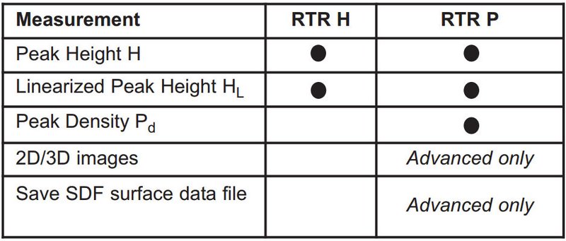
The PosiTector Replica Tape Reader (RTR) is a hand-held electronic instrument that measures burnished Testex Press-O-FilmTM replica tape to produce peak-to- valley surface profile height measurements. It consists of a body (Standard or Advanced) and probe (RTR-H or RTR-P).
PosiTector RTR-P models also measure peak density (Pd). Advanced RTR-P models generate 2D/3D images and SDF Surface Data Files.
A surface cleaned by abrasive blast is best described using two measured parameters: peak height and peak density.
Peak Height
- H – the average of the maximum peak-to-valley distances obtained by measuring the thickness of the replica tape
- HL – a more accurate peak-to-valley height measurement adjusted for tape non-linearity without the need to average 2 or more replicas. This method has the additional benefit of being able to extend the range of each grade of replica tape. See Linearize
Peak Density (RTR P only) Pd – the number of peaks per square millimeter or square inch. See Peak Density
![]() PosiTector RTR Kit Contents
PosiTector RTR Kit Contents![]()
|
|
The PosiTector RTR powers-up when the center navigation button ![]() is pressed. To preserve battery life, the Gage powers down after approximately 5 minutes of no activity. All settings are retained.
is pressed. To preserve battery life, the Gage powers down after approximately 5 minutes of no activity. All settings are retained.
NOTE: To ensure best accuracy, the user will be required to zero the probe every time the Gage is powered-up. It is therefore a good idea to clean the probe regularly with the included cleaning card. Cleaning is best performed when the Gage is powered down.
With the Gage powered down:
- Clean the probe with the included cleaning card.
- Power-up the Gage by pressing the center navigation
 button.
 - Zero the probe.
- Measure the included check shim to verify accuracy.
- Measure the burnished replica tape.
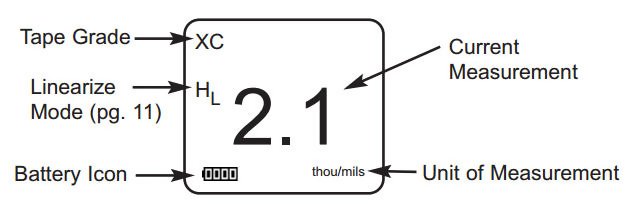
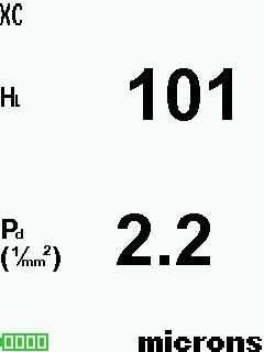
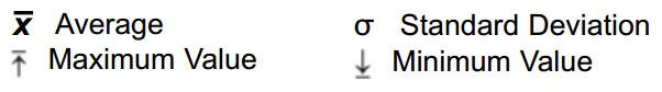
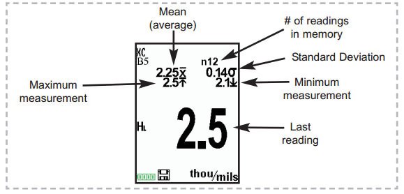
Typical Display
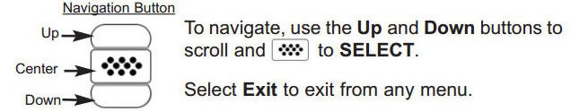
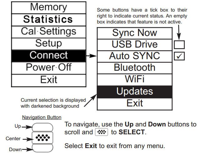
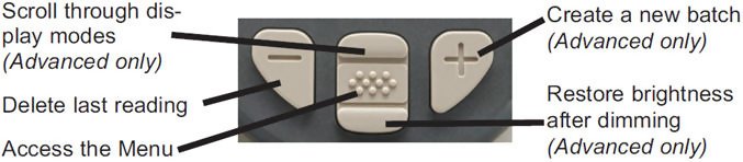
Gage functions are menu controlled. To access the Menu, power-up the Gage, then press the center ![]() navigation button.
navigation button.
NOTE: The center ![]() button is purposely recessed to help eliminate unintentional powering-up of the Gage.
button is purposely recessed to help eliminate unintentional powering-up of the Gage.
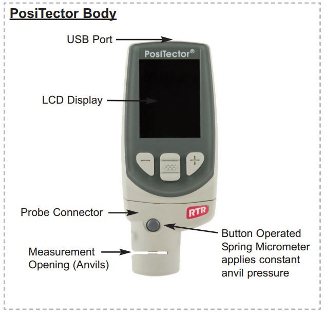
PosiTector Body
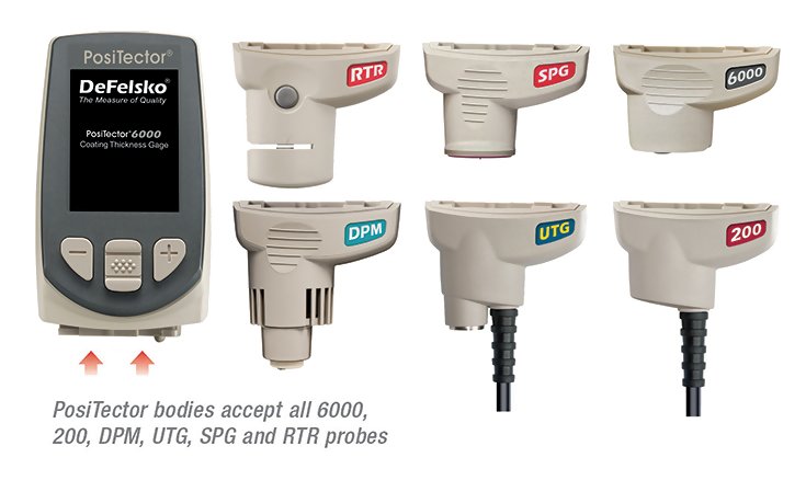
PosiTector bodies accept all interchangeable probes including surface profile (RTR/SPG), coating thickness (6000/200), environmental (DPM) and ultrasonic wall thickness (UTG) probes.
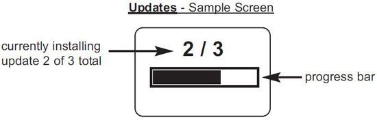
Updates: Keep your PosiTector current with software updates containing the latest features, functionality and probe compatibility.
Power Source: 3 AAA?alkaline, Lithium or optional Nickel-metal hydride (NiMH) rechargeable batteries. For best battery indicator results, ensure the appropriate Battery Type is selected in the Setup > Battery Type menu.
Wrist Strap: We recommend attaching and wearing the supplied wrist strap.
Plastic Lens Shield
The PosiTector display is covered with a thin plastic film for protection against fingerprints and other marks during shipment. This film, while usually removed before using the Gage, can be left in place to protect against paint overspray or debris. Replacements can be purchased.
 |
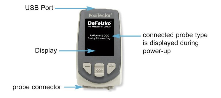
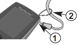
When powered-up the PosiTector automatically determines what type of probe is attached and does a self-check. To disconnect a probe from a body, slide the plastic probe connector horizontally (in the direction of the arrow) away from the body. Reverse these steps to attach a new probe. NOTE: It is not necessary to power-down the gage when interchanging probes. |
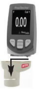
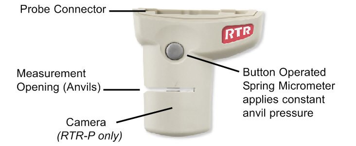
PosiTector RTR probe (RTR-P shown)
Additionally, the PosiTector accepts a number of probe types including magnetic and eddy current coating thickness, surface profile, environmental and ultrasonic wall thickness probes. Perform the latest software Updates to ensure probe compatibility with your Gage. For the latest information on probe interchangeability see www.defelsko.com/probes
PosiTector body accepts all 200, 6000, SPG, RTR, DPM and UTG probes.
PosiTector SmartLink Compatible (RTR-H probes only)
A smart new way to measure!
- wirelessly connect RTR-H probes to your smart device
- turn your cell phone or tablet into a virtual PosiTector gage
- includes free PosiTector app
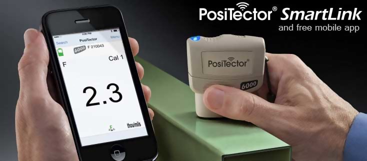
NOTE: RTR-P probes are not compatible with PosiTector SmartLink
PosiTector RTR probes include a Certificate of Calibration. For organizations with re-certification requirements, instruments may be returned at regular intervals for calibration.
DeFelsko recommends that customers establish calibration intervals based upon their own experience and work environment. Based on our product knowledge, data and customer feedback, a one year calibration interval from either the date of calibration, date of purchase, or date of receipt is a typical starting point.
Why is surface profle measurement important?
Steel surfaces are frequently cleaned by abrasive impact prior to the application of protective coatings. The resultant surface profile must be accurately assessed to ensure compliance with job or contract specifications. In the protective coatings industry, replica tape is widely used for quantifying surface profile.
Peak height and peak density are important factors in the performance of applied protective coatings. Low values may reduce coating bond strength (adhesion). High values may cause peaks to receive insufficient coverage and possibly rust prematurely and for the surface to be insufficiently wetted.
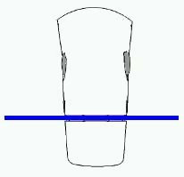
The figure below is a simplified example of why BOTH peak height AND peak density are important to the understanding of coating performance. The two surfaces have different geometries yet their height measurements are the same. Peak density measurements give a clearer picture of the surface available for bonding.
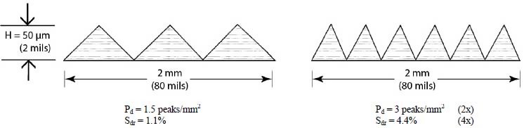
Both surfaces have the same measured peak-to-valley height. A second important measurable parameter, peak density, helps explain why coatings bond differently to each surface.
For these reasons, surface profile should be measured prior to coating application to ensure that it meets contract specifications.
![]() Press-O-Film Replica Tape
Press-O-Film Replica Tape![]()
Press-O-Film provides a simple way to obtain an impression of a surface for analysis. It consists of a layer of crushable plastic micro foam affixed to a 50.8 µm (2 mil) incompressible polyester film. When compressed against a roughened surface, the foam collapses and acquires an accurate impression, or reverse replica, of the surface.
Placing the compressed tape (replica) into the PosiTector RTR gives a measure of the average maximum peak-to-valley height of the surface roughness profile. The Gage automatically subtracts the thickness of the polyester substrate from all measurements. Press-O-Film is available in Coarse (C) and X-Coarse (XC) grades to accommodate measurements in different profile ranges.

Optical Grade Press-O-Film Replica Tape
For improved optical resolution and to reduce optical artifacts (see below tape comparison), this special grade of replica tape is available for use with the PosiTector RTR-P. It provides higher quality SDF surface data files than conventional Press-O-Film replica tape. It is available in both Coarse (C) and X-Coarse (XC).
- Prepare the test surface
- Burnish the replica tape
- Prepare the Gage
- Measure
 |
Prepare the test surface Locate a representative site for measurement. Clean the surface to be tested. DeFelsko recommends the use of the included putty to remove dust, debris, or residual blast media from the surface. Firmly press the putty onto the surface using your fingers, and remove. NOTE: Ensuring a clean surface is especially important when using the PosiTector RTR-P to measure peak density (Pd) and generate surface images. |
 |
Burnish the replica tape (create a replica) Select the appropriate grade of replica tape based on the target profile. See tape instructions for assistance. Pull a single adhesive-backed replica tape free of its release paper. A “bull’s eye” circle of paper should remain on the release paper (it is not used for measurement). |
 |
Prepare the Gage With the Gage powered-down, clean the measurement surfaces using the included cleaning card. Swipe the card through the opening a few times while firmly pressing both probe buttons to remove dust particles and residual tape adhesive. NOTE: Cleaning the anvils is especially important when using the PosiTector RTR-P to measure peak density (Pd) and generate surface images. If the cleaning card is damp, wait for the anvils to dry before measuring. |
Power-up the Gage by pressing the center navigation button. An image appears indicating that the probe requires zeroing.
Simultaneously press and hold both probe buttons firmly until the Gage beeps and the arrows point outward. Do not place anything in the measurement opening during this procedure.
Measure the included check shim to verify accuracy.
Ensure the correct grade of replica tape, C or XC, is displayed in the upper left corner of the LCD.
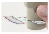 |
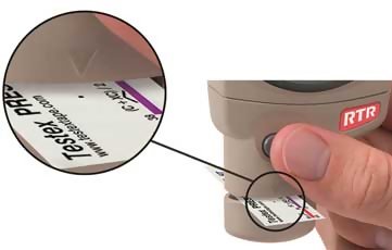
Measure Insert the burnished replica tape into the measurement opening. Ensure the tape is properly positioned so that the burnished region is centered within the opening in the probe with the adhesive (sticky) side down. To position the tape, move the tape to the back of the probe and align the two dots (printed on replica tape) with arrows on both sides of the measurement opening. |
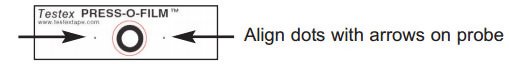
If you are using older tape that does not have the printed dots, simply align by centering the tape within the measurement opening.
Once positioned, firmly press both probe buttons simultaneously and hold until the Gage beeps and the measurement is displayed. During measurement, a constant anvil pressure is applied to the replica tape regardless of how hard the two buttons are pressed. The Gage automatically subtracts the 50.8 ?m (2 mil) of incompressible polyester film. No further adjustments are required.
![]() PosiTector RTR-H?models
PosiTector RTR-H?models ![]()
- Ensure tape is properly positioned.
- Firmly press both probe buttons simultaneously and hold until the Gage beeps and the surface profile height (HL)?measurement is displayed. The tape can now be safely removed.
![]() PosiTector RTR-H?models
PosiTector RTR-H?models ![]()
 |
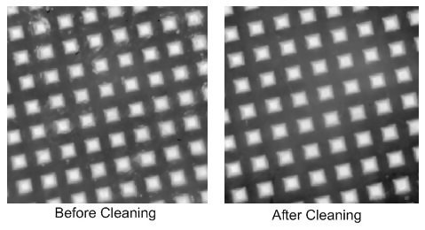
It is important to clean the anvils before each measurement when obtaining peak density (Pd) and generating surface images.
|
Several images of the foam surface are captured during each measurement. Image blurring will occur if the tape is touched or removed during this time.
- The surface profile height (HL)?measurement is immediately displayed. ?The tape can now be removed. ?An hour glass will display while peak density (Pd) and the associated 2D/3D images are being generated.
NOTE: Optical Grade Replica Tape provides higher quality SDF surface data files than conventional Press-O-Film replica tape. This special grade of tape recommended when taking measurements which will be exported as SDF images.
![]() Cleaning the probe opening (anvils)
Cleaning the probe opening (anvils) ![]()
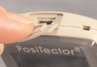
The probe contains two measuring surfaces that can become contaminated with dust particles and residual tape adhesive. It is therefore a good idea to clean the probe regularly with the included cleaning card. Cleaning is essential prior to performing a probe zero or a verification of accuracy. It is best performed when the Gage is powered down.
With the Gage powered-down, swipe the card through the opening a few times while firmly pressing both probe buttons.
The cleaning card can also be used to clean the surfaces of analog spring micrometers. Replacement cards are available from your dealer.
NOTE: Cleaning the anvils is especially important when using the PosiTector RTR-P to measure peak density (Pd) and generate surface images.
Example of a 2D surface image taken with a PosiTector RTR-P Advanced before and after cleaning the anvils with the cleaning card.
![]() Calibration & Verification of Accuracy
Calibration & Verification of Accuracy![]()
![]() Calibration
Calibration![]()
Gage calibration is typically performed by the manufacturer or accredited lab. All probes include a Certificate of Calibration.
![]() Verification of Accuracy
Verification of Accuracy![]()
Ensure that the probe has been cleaned with the included cleaning card and that the probe has been zeroed.
Verify accuracy of the peak height measuring system
Place the PosiTector RTR Check Shim into the probe opening. The average of several measurements should be within the combined tolerance of both the Gage and the shim. If not, the Gage may need to be returned to your dealer for service.
The check shim is specifically intended for all PosiTector RTR probes. The Gage is designed to measure burnished replica tape within a limited measuring range and automatically subtracts 50.8 µm (2 mil) from height measurements to account for the incompressible polyester film. Therefore plastic shims intended for other instruments such as coating thickness gages will not be measured properly.
Verify the peak density measuring system (RTR-P models only)
Place the Peak Density Check Tape into the probe opening. The peak density (Pd) result should be within tolerance specified on the tape. Ignore the peak height (H) result. If not, the Gage may need to be returned to your dealer for service..
Gage functions are menu controlled. To access the Menu, power-up the Gage, then press the center ![]() navigation button.
navigation button.
Below is a sample menu for a PosiTector RTR H Advanced model:
NOTE: The center ![]() button is purposely recessed to help eliminate unintentional powering-up of the Gage.
button is purposely recessed to help eliminate unintentional powering-up of the Gage.
The probe should be zeroed regularly to ensure best accuracy. While the user will be required to zero the probe every time the Gage is powered-up. The Zero menu item allows the procedure to be performed at more regular intervals. It is particularly useful during long measurement sessions.
Clean the probe with the included cleaning card before performing a probe zero.
- Select Zero from the Cal Settings menu
- Simultaneously press and hold both probe buttons firmly until the Gage beeps and the arrows point outward.
Do not place anything in the measurement opening during this procedure.
SHORTCUT:
- Simultaneously press and hold both probe buttons firmly until the Gage beeps and displays “0”. This can be performed from the main measurement screen without having to access the menu.
When selected the gage instructs the probe to take a picture and store this image as a reference. This image is used with subsequent measurements to compensate for irregularities in the optical path within the probe. This operation is only required if the generated images can not be cleaned up by cleaning the anvils with the cleaning card.
- Selects a replica tape grade. Required when Linearize mode (HL) is ON.
- C - Coarse
- XC - X-Coarse (default)
NOTE:
Coarse Minus and X-Coarse Plus grades are not supported in Linearize mode since the only function of these two grades is to improve upon the accuracy of C tape at its low end and XC tape at its high end, something the PosiTector RTR will automatically do when measuring HL. When Linearize mode is OFF, the PosiTector RTR will measure all four grades of replica tape just like a conventional spring micrometer.
This is the default measurement mode. Linearize mode is ON when this box is ticked and the "HL" appears on the display.
An undesirable characteristic of replica tape is that measurements made with analog spring micrometers are most accurate near the middle of each grade's range and least accurate at the outer ends of each grade's range. That is why two other grades, Coarse Minus and X-Coarse Plus, are used to check and, if necessary, adjust measurements at the lower and upper ends of the primary range of 20 - 115 µm (0.8 - 4.5 mils).
Inside the primary range, the upper end of Coarse grade’s range and the lower end of X-Coarse grade’s range share a 38 - 64 ?m (1.5 - 2.5 mil) "overlap" region. Current Testex instructions describe a relatively complicated and time consuming procedure (the average of one reading using Coarse grade and one reading using X-Coarse grade) that is used to knit the Coarse and X-Coarse sub-ranges together to achieve reasonably accurate readings over the primary range. This method is a compromise between accuracy and ease of use.
-
When the Linearize box is NOT ticked, the PosiTector RTR displays a height value of H comparable to the value an analog spring micrometer would display after the 50.8 ?m (2 mil) of incompressible polyester substrate has been subtracted. In other words, it is the average of the maximum peak-to-valley distances obtained by measuring the thickness of the replica tape without any correction.
-
When the Linearize box IS ticked, the PosiTector RTR displays a more accurate peak-to-valley height measurement HL that has been adjusted for the non-linearity of replica tape. There is no need to average 2 or more replicas from different grades of tape AND there is no need to subtract the 50.8 ?m (2 mil) of incompressible polyester substrate. Ensure the proper tape grade, C or XC, has been selected and appears in the upper left corner of the display.
During measurement, if the linearized measurement falls outside of the selected tape grade's range, the Gage will suggest a more suitable tape grade to perform the measurement.
Reset (soft reset) restores factory settings and returns the instrument to a known condition. The following occurs:
- All batches, stored measurements, images, batch names and screen captures are erased.
- Menu settings are returned to the following:
|
|
* PosiTector RTR-P models only
Perform a more thorough Hard Reset by powering down the Gage, waiting several seconds, then simultaneously holding both the center ![]() and (+) buttons until the Reset symbol
and (+) buttons until the Reset symbol ![]() appears. This returns the instrument to a known, “out-of-the-box” condition. It performs the same function as a menu Reset with the addition of:
appears. This returns the instrument to a known, “out-of-the-box” condition. It performs the same function as a menu Reset with the addition of:
- Bluetooth Pairing info is cleared.
- Menu settings are returned to the following:
|
Note: Date, Time and WiFi settings are not affected by either Reset.
Displays the gage body/probe details including serial numbers, PosiSoft.net registration key,remaining memory capacity for storage of readings, date and time and software packages.
For security purposes, the registration key is required to add the Gage to your PosiSoft.net account.
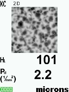
When selected, the Gage will measure and display peak density (Pd), the number of peaks per unit area.
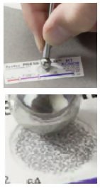
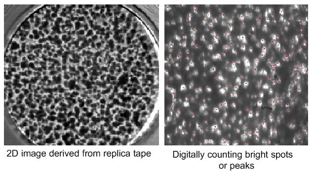
The PosiTector RTR-P projects light through the replica tape and captures a two-dimensional black and white image.
Peak density be determined by simply counting the bright spots on the image. The intensity of light that passes through the replica tape is inversely proportional to the thickness of the compressed foam. The below photograph of a back-lit piece of replica tape reveals light areas of higher compression (peaks) and dark areas of lower compression (valleys).
![]() 2D
2D ![]() (RTR-P Advanced models only)
(RTR-P Advanced models only)![]()
Displays a two-dimensional (2D) black and white image of the replicated surface. ?When Memory is on, this thumbnail image is stored with each reading for inclusion into inspection reports.
![]() 3D
3D ![]() (RTR-P Advanced models only)
(RTR-P Advanced models only)![]()
Displays a low-resolution color three-dimensional (3D) image of the replicated surface. ?When Memory is on, this thumbnail image is stored with each reading for inclusion into inspection reports.
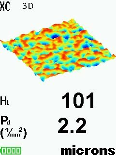
NOTE: Press the Up navigation button to scroll between 2D and 3D images if the image does not automatically appear on the display.
![]() Save SDF (RTR-P Advanced models only)
Save SDF (RTR-P Advanced models only)![]()
Stores a Surface Data File (SDF) to the USB Drive. This provides a means to perform a more detailed analysis of the surface using third party image rendering/analysis software such as Gwyddion or MountainsMap. Select Save?SDF within the Memory menu. A progress bar will appear while the SDF is saved (approximately 2 minutes).
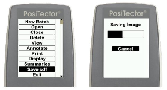
Only a single SDF?can be stored at a time. Each saved image overwrites the previous one. The SDF can be accessed when connected to a computer (see?USB Drive). The SDF is stored in the root directory named with the format: rtr_{datetime}.sdf
NOTE: Cleaning the anvils prior to measurement is especially important when using the PosiTector RTR-P to generate surface images.
Optical Grade Replica Tape provides higher quality SDF surface data files than conventional Press-O-Film replica tape. This special grade of tape is recommended when taking measurements which will be exported as SDF images.
Below is an example of a PosiTector generated SDF opened in Gwyddion - a free and open source software image rendering software. www.gwyddion.net
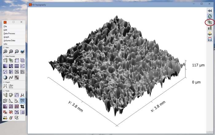
Garnet 30/60 Grit blast cleaned surface
More examples are available at: www.defelsko.com/rtr/rtr_surface_data_file.htm
SDF Specifications
- Range: 125 um
- Field of view: 4x4 mm
- Image size: 1024x1024x12bit
- Lateral sampling interval: 3.8 um
This option causes the display to read upside down allowing for alternate positioning techniques.
![]() White on Black (Advanced models only)
White on Black (Advanced models only)![]()
Inverts the LCD display to white on a black background to provide better readability in some surroundings.
![]() Backlight (Advanced models only)
Backlight (Advanced models only)![]()
Selects display brightness (Sun, Normal or Night). All settings will dim slightly after a period of no activity to conserve battery life. Press the Down button to brighten the display.
Sound: When checked (default), the gage will emit various sounds for activities such as successful measurement and for button presses. Untick to turn sound off.
Set Clock: All measurements are date and time stamped (24 hour format) when stored into memory. It is therefore important to keep both the date and time current using this menu option. Use the Up and Down buttons to scroll, and the (-) and (+) buttons to adjust a value. The instrument’s date and time can also be viewed in Gage Info
Converts the display from inch to metric or vice versa. Stored measurements in memory are not converted. Switching units will turn off Statistics view and closes Memory.
Selects the type of batteries used in the instrument from a choice of “Alkaline”, “Lithium” or “NiMH” (Nickel-metal hydride rechargeable). If NiMH is selected, the instrument will trickle charge the batteries while connected via USB to a PC or optional AC charger (Gage must be powered ON). The battery state indicator icon is calibrated for the selected battery type. No damage will occur if the wrong battery type is selected.
NOTE: DeFelsko recommends eneloop (NiMH) rechargeable batteries.
Converts displayed and printed words to the selected language.
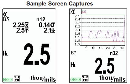
A statistical summary will appear on the display. Remove the last measurement by pressing the (-) button. Press (+)?to clear statistics.
The PosiTector RTR has internal memory storage for recording measurement data. Stored measurements can be reviewed on-screen or accessed via computers, tablets and smart phones. Measurements are date and time-stamped.
Button functions with Memory on:
Standard models store up to 250 readings in one batch.
The Memory Menu includes the following options:
- On: turns memory on and begins recording
- Off: stops recording (stored readings remain in memory)
- Clear: removes all readings from memory
- View: lists group statistics and all stored readings on the display. It will begin by showing statistics based on all readings in memory. Use the Up and Down buttons to scroll through all readings. Press to exit.
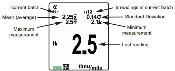
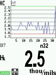
Standard Model display with Memory ON shows measurement statistics:
Advanced models store 100,000 readings in up to 1,000 batches.
The Memory Menu includes the following options.
New Batch
Closes any currently opened batch and creates a new batch name using the lowest available number. For example, if only Batch 1 and Batch 3 exist, then Batch 2 would be created and made the current batch. The ![]() icon appears and basic statistics are displayed. Each measurement will be displayed and stored into this new batch. On screen statistics are immediately updated with each measurement. New batch names are date stamped at the time they are created. Each reading is also data/time stamped.
icon appears and basic statistics are displayed. Each measurement will be displayed and stored into this new batch. On screen statistics are immediately updated with each measurement. New batch names are date stamped at the time they are created. Each reading is also data/time stamped.
Shortcut: When a batch is open, press (+) to create a new batch
NOTES:
- Remove the last reading from the current open batch by pressing (-).
- If memory is ON, continuous measurements can be taken but results will not be stored in memory.
- Each batch can contain a maximum of 10,000 readings.
 |
Open: Selects a previously created batch name to open and make current. If it contains measurements, onscreen statistics will immediately reflect values calculated from this batch. Close: Stops the recording process, closes the current batch, and removes batch information from the display. Delete: Removes a batch completely from memory. The name is deleted and all measurements are erased. View: Scroll using the Up or Down buttons through information, statistical summary, and a list of each reading in the currently opened batch. Press |
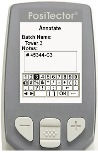
Create meaningful batch names and enter notes directly on the Gage using a familiar onscreen QWERTY keyboard.
Use the Gage's navigation and (-)(+) buttons to enter annotations.
Annotations can be synchronized with PosiSoft.net and are included in all PosiSoft reports see Accessing Stored Measurement Data
NOTE: Annotations can also be created using PosiSoft.net or PosiSoft Mobile
![]() Print
Print![]()
Sends a statistical summary and individual measurements to the optional Bluetooth wireless printer.
NOTE: To cancel printing, press and hold the (-) and (+) buttons simultaneously.
![]() Display (appears only if a batch is currently open)
Display (appears only if a batch is currently open)![]()
The following user selectable display options are available:
|
|
None: Default screen shows statistics SHORTCUT: When a batch is open, press Up to scroll through the above display options. |
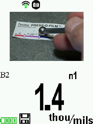
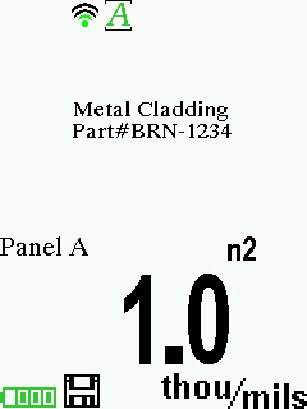
NOTE: PosiSoft.net and PosiSoft Mobile are used to insert an Image and Notes into a batch.
|
![]() Summaries (Advanced models only)
Summaries (Advanced models only)![]()
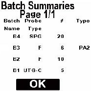
Displays a summary of all stored batches including the name, probe type, number of readings and type.
In the following example, Batch 3 (B3)? indicates an “F” 6000 coating thickness probe was used to record a total of “6” readings in “PA2” mode.
Press both (-)(+) buttons at any time to capture and save an image copy of the current display. The last 10 screen captures are stored in memory and can be accessed when connected to a computer (see PosiSoft USB Drive).
![]() Accessing Stored Measurement Data
Accessing Stored Measurement Data![]()
PosiSoft solutions for viewing, analyzing and reporting data:
- PosiSoft USB Drive - connect the PosiTector to a PC/Mac using the supplied USB cable to access and print stored readings, graphs, photos, notes and screen captures. No software or internet connection required. USB Drive must be selected.
- PosiSoft.net - a free web-based application offering secure centralized storage of PosiTector readings. Access your data from any web connected device. Go to: www.PosiSoft.net
- PosiSoft 3.0 - Desktop Software for downloading, viewing and printing your measurement data.
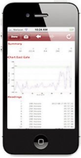
- PosiSoft Mobile (Advanced models only) - access readings, graphs, capture photos and update annotations through WiFi enabled devices, such as tablets, smart phones and computers.
![]() PosiSoft Desktop Manager (PDM)
PosiSoft Desktop Manager (PDM)![]()
A small Windows based application which allows automatic two- way communication (synchronization) between the Gage and PosiSoft.net (internet connection required). When installed, PDM runs as a start-up application and resides in the Windows notification area (system tray) of a PC. PDM is available as a free download within your PosiSoft.net account or at www.defelsko.com/downloads
Register your Gage on PosiSoft.net to take full advantage of your Gage’s capabilities. See www.PosiSoft.net
NOTE: PDM is not required for WiFi enabled gages.
To enhance the operation of your Gage, all PosiTector users have access to the features provided by PosiSoft.net. It is a web-based application offering secure centralized management of readings.
After (1) a user account has been created, (2) a Gage has been registered, and (3) the PosiSoft Desktop Manager is downloaded and installed onto a Windows PC (not required for WiFi connected gages), synchronization of measurement data can be performed either manually or automatically whenever the PosiTector is connected to a web enabled PC (USB cable or Bluetooth wireless technology) or WiFi network (Advanced gages only). Gage measurements stored in memory are uploaded; images and batch notes are synchronized.
Uploaded data can be manipulated using a standard internet web browser from any location in the world - job site or head office. Reports and graphs with annotations and corporate logo can be generated. Data can be exported to XML or CSV (comma delimited) text files.
Measurement data can be shared with authorized users via a secure login from any computer and most web enabled devices including smart phones.
NOTE: A PosiSoft.net account is not required to Update your PosiTector. Simply download and install PosiSoft Desktop Manager at www.defelsko.com/downloads
PosiSoft 3.0 Desktop Software that can be installed onto your Windows PC and allows the user to download, view, print and analyze their measurement data.
Reports and graphs with annotations and corporate logo can be generated. Data can be exported to XML or CSV (comma delimited) text files.
NOTE: PosiSoft 3.0 is available for use with DeFelsko’s complete line of electronic instruments and is available for download at www.defelsko.com/posisoft
Is a Gage-based software application featured in all PosiTector Advanced instruments (serial numbers 730,000+).
PosiSoft Mobile allows users to:
• browse stored measurement data including notes, images, statistics and charts
• update batch names/notes using your mobile device's keyboard
• insert images directly into Gage batches using your mobile device's camera or image library
• remotely view the live display of a working PosiTector & more
PosiSoft Mobile can be accessed from any WiFi enabled device using a standard web browser. Ideal for use with devices such as Windows Phone/Mobile, Blackberry (RIM), Android, Apple iOS and more.
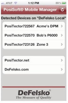
In addition to browser based access, PosiSoft Mobile Managers are available for Apple iOS and Android users.
See www.defelsko.com/wifi/wifi_mobile
Synchronizing (Sync) is the process whereby PosiTector stored measurement data uploads to PosiSoft.net (from both Standard and Advanced models) while images and batch notes are downloaded to the Gage (Advanced model only). This transfer occurs when the Gage is connected via USB, Bluetooth or directly through your WiFi router/hotspot via WiFi. It can be triggered either manually (USB, Bluetooth or WiFi) or automatically (USB only).
When selected, the Gage immediately synchronizes stored measurement data via USB, Bluetooth or WiFi to PosiSoft.net (internet connection required). PosiSoft Desktop Manager is required when using USB or Bluetooth.
Multiple gages can be synchronized simultaneously when connected using multiple connections (for example two gages connected via USB and one gage connected via WiFi or Bluetooth).
Allows the Gage to automatically synchronize stored measurements with PosiSoft.net when initially connected via USB to an internet connected PC running PosiSoft Desktop Manager.
Additional measurements added to memory while connected are synchronized only when the USB cable is disconnected, then reconnected or when the Sync Now option is selected.
Universal Serial Bus (USB) is a specification for communication between devices and a host controller (usually a personal computer). USB has effectively replaced a variety of interfaces such as serial and parallel ports.
The PosiTector uses a USB mass storage device class which provides a simple interface to retrieve data in a manner similar to USB flash drives, cameras or digital audio players.
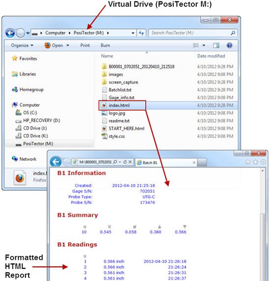
When checked, any computer can view readings stored in memory by navigating a virtual drive labeled “PosiTector” using the included USB cable.
A formatted HTML report is viewed by selecting the "index.html" or “START_HERE.html” file found in the root directory. Optionally, text ".txt" files located in each batch folder provide access to measurement values. Stored readings and graphs can be viewed or copied using universal PC/Mac web browsers or file explorers.
When your PosiTector is first connected to your Windows PC via a USB cable, an enumeration process is started that installs device drivers without re-booting your computer. You may see several pop-up windows in the taskbar at the bottom right of your screen. Wait for the entire process to be completed before proceeding.
NOTE: When connected, power is supplied through the USB cable. The batteries are not used and the body will not automatically power down. If rechargeable (NiMH) batteries are installed, the Gage will trickle charge the batteries.
![]() Retrieving stored screen captures
Retrieving stored screen captures![]()
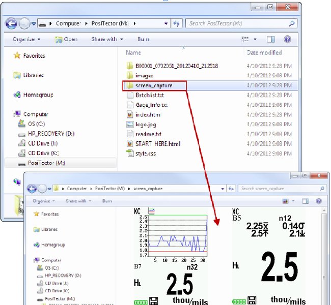
The last 10 screen captures stored in memory can be accessed by navigating to the “screen_capture” directory within the “PosiTector” virtual drive.
![]() Bluetooth (Advanced models only)
Bluetooth (Advanced models only)![]()
![]()
PosiTector Advanced models have Bluetooth functionality to:
- Communicate with the Posisoft Desktop Manager (PDM) in lieu of a USB cable.
- Stream individual readings to a computer or Bluetooth wireless printer as they are taken.
- Print to the optional battery powered Bluetooth wireless printer.
- On: Turns Bluetooth functionality On. When selected, the icon will appear on the display. To deactivate Bluetooth, select Off
- Pairing: The Gage and receiving device must be paired before stored or streamed readings can be transmitted. For pairing instructions, see www.defelsko.com/bluetooth/
- Info: Lists information about your current Bluetooth connection, including the currently paired device and MAC address.
- Stream: When checked, the Gage will stream readings to the paired Bluetooth Device as they are taken. Readings can be streamed as they are taken to the optional Bluetooth wireless printer or third-party computer software.
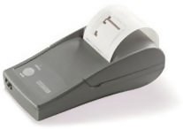 |
PosiTector Advanced models can output to the optional battery powered Bluetooth wireless printer one of two ways:
|
Begin by entering the Connect > Bluetooth menu. Turn Bluetooth ON and “Pair” the PosiTector to the printer. See: www.defelsko.com/bluetooth/
Streaming: In the Connect > Bluetooth menu, select the “Stream” tick box. All readings will now be simultaneously displayed on the LCD and sent to the printer.
Printing: In the Memory menu, select Print.
Allows wireless communication with devices such as tablets, smart phones and computers connected to your local wireless network or portable mobile hot spot. See www.defelsko.com/WiFi
On/Off ![]() : Turns WiFi functionality On. When selected, the
: Turns WiFi functionality On. When selected, the ![]() icon will appear on the display. To deactivate WiFi, select Off.
icon will appear on the display. To deactivate WiFi, select Off.
Access Point ![]() : Connect your smart device/computer to a PosiTector Advanced body wirelessly without the need for a separate network. Wirelessly import readings into PosiSoft 3.0 Desktop Software or access PosiSoft Mobile in the field or whenever a WiFi network is not available or out-of-range.
: Connect your smart device/computer to a PosiTector Advanced body wirelessly without the need for a separate network. Wirelessly import readings into PosiSoft 3.0 Desktop Software or access PosiSoft Mobile in the field or whenever a WiFi network is not available or out-of-range.
To enable, select Access Point from the Connect > WiFi menu. The Access Point icon ![]() will display in the upper left of the PosiTector display.
will display in the upper left of the PosiTector display.
![]() Securing your Access Point
Securing your Access Point ![]()
- To ensure the PosiTector is only accessible to authorized devices, it is important that you enter a passphrase (password) for the Access Point. The default Passphrase is password.
- In the Connect > WiFi > Setup menu, select AP Passphrase.
- Press button to display on-screen keyboard. Enter a Passphrase for the Access Point. The Passphrase will be required for all devices connecting to the PosiTectors Access Point.
- The PosiTector is now visible to all WiFi enabled devices. Simply connect your devices WiFi to the new PosiTector Access point. All PosiTectors are uniquely identified by their respective gage body serial numbers.
![]() AP Channel - Default Channel: 6
AP Channel - Default Channel: 6![]()
- For most users the default channel will not have to be altered. If you are experiencing poor connection or are unable to connect, try another channel.
- In the Connect > WiFi > Setup menu, select AP Channel.
- Press the UP center navigation button to highlight the channel. Use the (-) or (+) buttons to change the channel. Press the DOWN navigation button and select OK. Press the button.
![]() Import readings into PosiSoft 3.0 Desktop Software
Import readings into PosiSoft 3.0 Desktop Software![]()
- From the PosiSoft 3.0 menu, select Import > From Gage. All connected gages will display their unique serial number. Measurement data will be displayed upon completion of the import.
- The time it takes for import will depend on the number of Batches and measurements present within the gage. Imports generally take no longer than a few seconds.
- Batches are not erased from the gages memory during import. They remain on the gage until they have been deleted by the user.
- For more information regarding PosiSoft 3.0: http://www.defelsko.com/posisoft/posisoft_software.htm
![]() Accessing your PosiTector PosiSoft Mobile
Accessing your PosiTector PosiSoft Mobile![]()
- For use on Apple iOS and Android devices:
- PosiSoft Mobile Manager apps exist for Apple iOS and Android users. Simply download the App from the Apple App Store or Google Play.
- Once your smart device/computer has been connected to the PosiTector Access Point, open the PosiSoft Mobile Manager app. Select your PosiTector from the list to open PosiSoft Mobile.
- For use with all WiFi enabled devices:
- Any WiFi enable device connected to the PosiTector Access Point can view the instrument’s built-in PosiSoft Mobile web interface. Using your device’s web browser, enter the IP address of your PosiTector to access the features of PosiSoft Mobile.
- In the Connect > WiFi menu, select Information to view the IP address associated with your PosiTector.
- Enter the displayed IP address into your devices web browser exactly as it appears. Example: 192.168.0.1:8080
- For more information regarding PosiSoft Mobile: http://www.defelsko.com/posisoft/posisoft_mobile.htm
Networks: The Gage will allow the user to add a new network and will automatically check for available local networks. Available networks detected by the Gage are listed on the screen along with any networks that the Gage has previously been connected to that are not currently within connection range.
- Information: Gage displays information about the local WiFi network connection including:
- SSID: the network’s name
- State: displays if the Gage is connected to the network or not
- IP Address: the network’s IP Address. Users can enter this number into a web-browser of any WiFi enabled device that is connected to the same network in order to view the Gage’s synced batches through PosiSoft Mobile.
- Setup: Allows user to setup a WiFi connection
- IP Settings: enter the IP information as follows.
- IP Type (DHCP or Static), IP Address, Gateway, Netmask, DNS1, DNS2.
- Server Enable: enables a connection between the network and the Gage.
- Gage Name: enter a name for the Gage (up to 14 Characters).
- WiFi Reset: erases all WiFi setting
Determines if a software update is available for your Gage. If an update is available, a prompt will appear allowing the user to choose to perform the update at this time or not.
To perform an update the Gage must be connected to an internet connected PC with PosiSoft Desktop Manager or WiFi network.
IMPORTANT: Ensure that stored measurements are backed up to a PC or PosiSoft.net. The Gage may perform a Hard Reset after completion of the update and ALL?readings in memory would be erased.
![]() Do Not unplug the gage during the update operation.
Do Not unplug the gage during the update operation.
NOTE: RTR-P probes can also be updated via this method. ?Ensure the probe is connected when checking for available updates.
Current gage and probe software revision information is available within the Gage Info menu option.
![]() Power Supply / Battery Indicator
Power Supply / Battery Indicator![]()
Power Source: 3 AAA?alkaline, Lithium or optional Nickel-metal hydride (NiMH) rechargeable batteries. For best battery indicator results, ensure the appropriate Battery Type is selected in the Setup > Battery Type menu.
The battery indicator ![]() displays a full bar with fresh alkaline or fully charged batteries installed. As the batteries weaken, the bar will be reduced. When the battery symbol is low
displays a full bar with fresh alkaline or fully charged batteries installed. As the batteries weaken, the bar will be reduced. When the battery symbol is low ![]() the Gage can still be used, but the batteries should be changed or recharged at the earliest opportunity. The Gage will turn off automatically when batteries are very low, preceded by a Low Battery Warning on the display.
the Gage can still be used, but the batteries should be changed or recharged at the earliest opportunity. The Gage will turn off automatically when batteries are very low, preceded by a Low Battery Warning on the display.
![]() To retain all user settings and stored memory readings, only replace the batteries after the instrument has powered-down. Battery performance decreases at low temperatures.
To retain all user settings and stored memory readings, only replace the batteries after the instrument has powered-down. Battery performance decreases at low temperatures.
Rechargeable Battery Pack
- 4 - AAA eneloop batteries
The PosiTector can operate on rechargeable batteries and DeFelsko recommends the use of eneloop (NiMH) rechargeables. eneloop batteries combine the advantages of regular rechargeable batteries and disposable (Alkaline) batteries. They discharge very slowly and can be stored for long periods without having self discharge concerns. Eneloop batteries come pre-charged and ready to use immediately. See: www.eneloop.info
![]() AC Power Cable Kit
AC Power Cable Kit![]()
An optional AC Power Cable Kit is available for continuous operation or battery charging through the PosiTector’s built-inUSB port. This kit supplies several alternate power solutions for your battery-operated PosiTector. They allow the gage to operate continuously without the need for batteries.
Use the usb cable alone to connect a PosiTector to your PC's built-in USB port that acts as a continuous power source. Or connect the cable to the included power adaptor which plugs into any AC wall electrical outlet, 110 or 220V.
A selection of electrical plugs is included which are capable of dealing with most country’s outlets.The USB cable provided can also be used for Accessing Stored Measurement Data.
A USB Cable is provided with every PosiTector. The USB cable can also be used for Accessing Stored Measurement Data via the PosiTector USB Port or to a connect to a PC's built-in USB port to act as a continuous power source. Replacement USB cables are available.
- Bluetooth Printer
- Nylon Case
- Convenient soft shell nylon case for carrying a PosiTector. Case has compartments for Certificates of Calibration, instruction manuals and other accessories.
- Protective Lens Shield
- One lens shield is included with every PosiTector instrument. Additional package of five (5) thin plastic lens shields are available and ideal for protecting the PosiTector display from paint and overspray.
- Testex Tape
- To create a reverse replica of the surface.
- Tape Grades: Coarse and X-Coarse
- Stainless Steel Burnishing Tool
- To burnish testex tape.
- Cleaning Cards
- To clean residual adhesive and debris from the anvils.
- Surface Cleaning Putty
- To clean the test surface of debris.
- Check Shim
- To verify accuracy.
- PosiTector RTR Models:
- * Standard:? H1 | * Advanced:?H3
- Measuring Range:
- 20 – 115 um | 0.8 – 4.5 mils
- Accuracy (H):
- +/- 5 um | +/- 0.2 mils
- Resolution:
- 1 um | 0.1 mil
- Anvil Pressure:
- 110 grams-force | 1.1 Newtons
- Anvil Size:
- Ø6.25 mm | Ø0.25 inch
- Gage Size:
- 152 x 61 x 28 mm | 6” x 2.4” x 1.1”
- Weight: (without batteries)
- 140 g | 4.9 oz
- Temperature Range:
- 0° to 40°C | +32° to +104°F
- Conforms to:
- ASTM D4417, ISO?8503-5, NACE RP287, SSPC-PA 17, SP6, SP10, SP11-87T and others
- ASTM D4417, ISO?8503-5, NACE RP287, SSPC-PA 17, SP6, SP10, SP11-87T and others
This device complies with part 15 of the FCC Rules. Operation is subject to the following two conditions: (1) This device may not cause harmful interference, and (2) this device must accept any interference received, including interference that may cause undesired operation.
Before returning the Gage for service
- Install new or newly recharged batteries in the proper alignment as shown within battery compartment.
- Clean the measurement anvils using the cleaning card.
- Perform a Hard Reset.
- Measure the check shim to verify accuracy.
IMPORTANT:
If you must return the Gage for service, please fill out and include the Service Form located at www.defelsko.com/support with the Gage. Be sure to describe the problem fully and include measurement results, if any. Also include the probe, your company name, company contact, telephone number and fax number or email address.
![]() Limited Warranty, Sole Remedy and Limited Liability
Limited Warranty, Sole Remedy and Limited Liability![]()
DeFelsko's sole warranty, remedy, and liability are the express limited warranty, remedy, and limited liability that are set forth on its website: www.defelsko.com/terms