DeFelsko PosiTector UTG Ultrasonic Wall Thickness Gages
DeFelsko PosiTector UTG Ultrasonic Wall Thickness Gages Instruction Manual with Videos
|
|

![]() Introduction
Introduction![]()
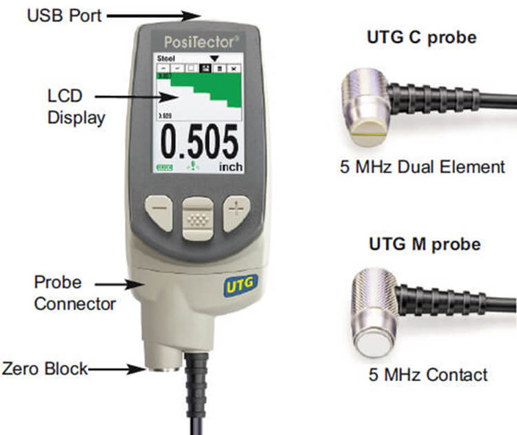
The DeFelsko PosiTector UTG is a hand-held Ultrasonic Thickness Gage that uses the non-destructive ultrasonic pulse-echo principle to measure the wall thickness of a wide variety of materials. It consists of a body (Standard or Advanced) and probe (UTG C or UTG M).
PosiTector UTG Kit Contents
|
|
![]() Quick Start
Quick Start![]()
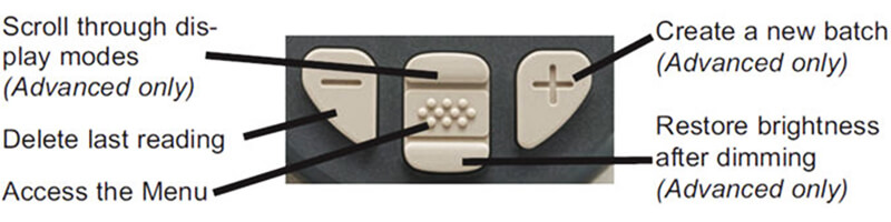
The DeFelsko PosiTector UTG powers-up when the center navigation![]() button is pressed. To preserve battery life, the instrument powers down after approximately 5 minutes of no activity. All settings are retained.
button is pressed. To preserve battery life, the instrument powers down after approximately 5 minutes of no activity. All settings are retained.
- Remove the protective rubber cap from the probe.
- Power-up Gage by pressing the center navigation button.
- Zero the probe
- Select the correct velocity of sound
- Measure the part
Protective Cap DeFelsko PosiTector UTG models are shipped with a protective plastic cap over the probe. Remove this cap prior to use. Replace it when the instrument is not in use to protect the probe. |
|
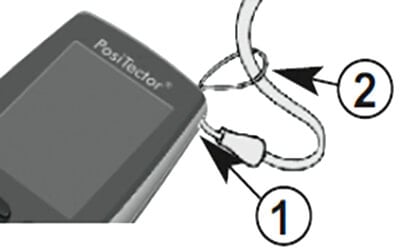
Wrist Strap We recommend attaching and wearing the supplied wrist strap. |
 |
![]() Certification
Certification![]()
All DeFelsko PosiTector UTG probes include a Certificate of Calibration. For organizations with re-certification requirements, instruments may be returned at regular intervals for calibration.
DeFelsko recommends that customers establish calibration intervals based upon their own experience and work environment. Based on our product knowledge, data and customer feedback, a one year calibration interval from either the date of calibration, date of purchase, or date of receipt is a typical starting point.
![]() Probes
Probes![]()
When powered-up, the PosiTector automatically determines which probe is attached and does a self-check.
To disconnect a probe from a body, slide the plastic probe connector horizontally (in the direction of the arrow) away from the body. Reverse these steps to attach a different probe. It is not necessary to power-down the Gage when switching probes.
The PosiTector gage body accepts a wide variety of probe types including soluble salt, magnetic, eddy-current and ultrasonic coating thickness, surface profile, environmental, Shore hardness durometer and ultrasonic wall thickness probes. See www.defelsko.com/probes
PosiTector gage bodies accept all PosiTector SHD, 6000, 200, SPG, RTR, DPM and UTG probes easily converting from a shore hardness durometer to a coating thickness gage, surface profile gage, dew point meter or wall thickness gage
Ultrasonic Thickness Probes - Theory of Operation
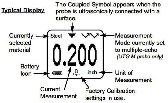
DeFelsko PosiTector UTG probes transmit an ultrasonic pulse into the material to be measured. This pulse travels through the material towards the other side. When it encounters an interface such as air (back wall) or another material, the pulse is reflected back to the probe. The time required for the pulse to propogate through the material is measured by the Gage, represented as t1 and t2 below. DeFelsko PosiTector UTG C and DeFelsko PosiTector UTG M (in single-echo |
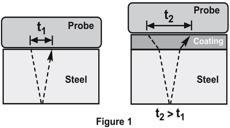 |
For uncoated materials t1 relates directly to material thickness. When a material is coated the propagation time is increased and is shown above as t2.
Coatings such as paint have a slower velocity of sound than that of metal. Thus the single-echo technique will produce a thickness result greater than the actual combined coating+metal thickness.
The DeFelsko PosiTector UTG M in multiple-echo mode![]()
![]() determines thickness by measuring the time between at least three consecutive back wall echoes.
determines thickness by measuring the time between at least three consecutive back wall echoes.
In the figure above, multiple-echo mode measures only the time between echoes. Regardless of whether the steel is coated or not, all times between echoes are the same. In multiple-echo mode, the Gage determines thickness by measuring t1+t2+t3, dividing it by six and then multiplying by the velocity of sound for that material. The resultant thickness calculation made by the instrument is therefore an accurate measurement of the steel thickness only, disregarding the coating thickness. |
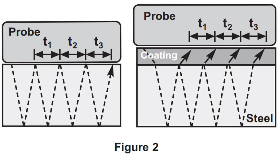 |
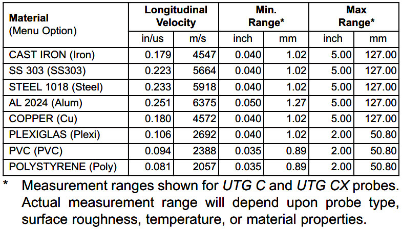
The velocity of sound is expressed in inches per microsecond or meters per second. It is different for all materials. For example, sound travels through steel faster (~0.233 in/µs) than it travels through plastic (~0.086 in/µs).
![]() How to Measure
How to Measure![]()
- Remove rubber cap from probe. Couplant (glycol gel - included) must be applied to the surface to be tested to eliminate air gaps between the wear face and the surface. A single drop of couplant is sufficient when taking a spot measurement.
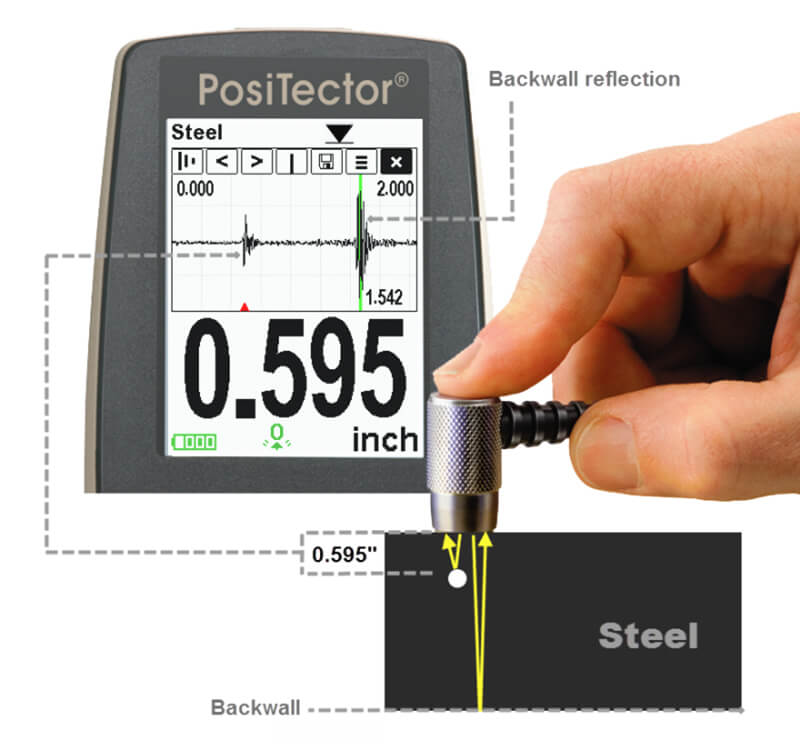
- Place the probe flat on the surface. Use moderate pressure to press against the top of the probe with the thumb or index finger. When the probe senses echoed ultrasound, a coupled symbol will appear on the display and thickness values will be displayed. While the probe is coupled, the PosiTector UTG continually updates the display.
- When the probe is removed from the surface, the last measurement will remain on the display.
Occasionally, excess couplant will remain on the probe when the probe is lifted from the surface. This may cause the PosiTector UTG to display a final measurement value different from those observed when the probe was on the surface. Discard this value and repeat the measurement.
![]() Surface Conditions
Surface Conditions![]()
Ultrasonic measurements are affected by the condition, roughness and contour of the surface to be tested.
Measurement results may vary on coarse surfaces. Where possible, it is recommended to seat the transducer on a smooth flat surface that is parallel to the opposite side of the material.
On rough surfaces, the use of a generous amount of couplant minimizes the surface effects and serves to protect the transducer from wear, particularly when dragging the probe across a surface.
During scanning operations, the probe can be become physically decoupled, that is physically separated, from the material, either due to the rough and/or scaly surface of the material or due to user operation. Avoid this by using the Smart Couple™ feature.
UTG M Probes: On smooth, uncoated metal surfaces the Gage (in multiple-echo?mode) may occasionally be unable to give a measurement result even when the "coupled"![]() symbol appears. Use additional couplant and lighter pressure on the probe when measuring. Alternatively, laying a plastic shim on the surface with couplant applied to both sides to simulate a painted surface will help produce a steel-only thickness measurement (multiple-echo mode). Switching the Gage to single-echo SE mode will also help produce a steel-only thickness measurement.
symbol appears. Use additional couplant and lighter pressure on the probe when measuring. Alternatively, laying a plastic shim on the surface with couplant applied to both sides to simulate a painted surface will help produce a steel-only thickness measurement (multiple-echo mode). Switching the Gage to single-echo SE mode will also help produce a steel-only thickness measurement.
![]() Calibration & Verification of Accuracy
Calibration & Verification of Accuracy![]()
Three steps ensure best accuracy.
- Calibration - typically performed by the manufacturer. All probes include a Certificate of Calibration.
- Verification of Accuracy - as done by the user on known reference standards such as calibration step blocks.
- Adjustment - to a known thickness or sound velocity for the material to be measured
Calibration
Calibration is the controlled and documented process of measuring traceable calibration standards and verifying that the results are within the stated accuracy of the Gage. Calibrations are typically performed by the Gage manufacturer or by a certified calibration laboratory in a controlled environment using a documented process. The standards used in the calibration are such that the combined uncertainties of the resultant measurement are less than the stated accuracy of the Gage.
Written Calibration Procedures are available online at no charge http://www.defelsko.com/resource/calibration-procedures
Verification
Gage accuracy can and should be verified using known reference standards of the material to be tested.
Verification is an accuracy check performed by the user using known reference standards. A successful verification requires the Gage to read within the combined accuracy of the Gage and the reference standards.
To guard against measuring with an improperly adjusted Gage, verify the Gage at the beginning and the end of each work shift. During the work shift, if the Gage is dropped or suspected of giving erroneous readings, its accuracy should be re-verified.
In the event of physical damage, wear, high usage, or after an established calibration interval, the Gage should be returned to the manufacturer for repair or calibration.
Adjustment
Adjustment, or Calibration Adjustment is the act of aligning the Gage's thickness readings to match that of a known reference sample.
![]() Menu Operation
Menu Operation![]()
Zero
- Make sure the instrument is on and the probe is wiped clean.
- Apply a single drop of couplant onto the zero plate located on the underside of the probe connector. DO NOT apply couplant directly onto the probe face.
- Select the Zero menu option and follow the on-screen prompts.
Calibration Adjustment
The DeFelsko PosiTector UTG is factory calibrated. In order for it to take accurate thickness measurements of a particular material it must be set to the correct sound velocity for that material. Be aware that material composition (and thus its sound velocity) can vary from stated tables and even between lots from a manufacturer. Adjustment to a sample of known thickness of the material to be measured ensures that the Gage is adjusted as close as possible to the sound velocity of that specific material. Samples should be flat, smooth and as thick as the maximum expected thickness of the piece to be tested.
The DeFelsko PosiTector UTG allows four simple adjustment choices. All four methods are based on the simple premise of adjusting the sound velocity. The first three adjustment methods make 1-point calibration adjustments to optimize the linearity of the DeFelsko PosiTector UTG over small ranges. The fourth method makes a 2-point calibration adjustment to allow for greater accuracy over a large range.
Thickness
The most common method of adjustment is to measure a sample of known thickness. Select a reference standard of material as close as possible in composition to the intended application. For best results, the thickness of the reference standard should be equal to or slightly greater than the thickness of the part to be measured.
- Apply a drop of couplant onto the reference standard.
- Measure the reference standard.
- Lift the probe. Select Thickness from the Cal Settings menu.
- Adjust the display down (-) or up (+) to the reference thickness.
- Press
 to the store the adjustment and exit.
Material
If a known thickness of the material is not available, but the material is known, this quick adjustment allows the user to load one of several preprogrammed material velocities.
 |
Velocity
If the sound velocity for the test material is known, the Gage can be adjusted to that specific sound velocity
- Select Velocity from the Cal Settings menu.
- Adjust the display down (-) or up (+) to the desired velocity. Holding the (-) or (+) buttons increases the rate of change.
- Presswhen the desired velocity is reached.
2 Pt Adjust
A 2-Point adjustment allows for greater accuracy while simultaneously adjusting probe zero. Select two reference standards as close as possible in composition to the intended application. For best results, the thickness of the thicker reference standard should be equal to, or slightly greater than the thickest part to be measured. The thickness of the thinner reference standard should be as close as possible to the lower end of the expected measurement range.
- Select 2 Pt Adjust from the Cal Settings menu.
- Measure the thinner reference sample.
- Lift the probe from the sample and adjust the display down (-) or up (+) to the expected thickness.
- When the expected thickness is reached, press
- Measure the thicker reference sample.
- Lift the probe from the reference sample and adjust down (-) or up (+) to the expected thickness.
- Pressto store the adjustment and exit.
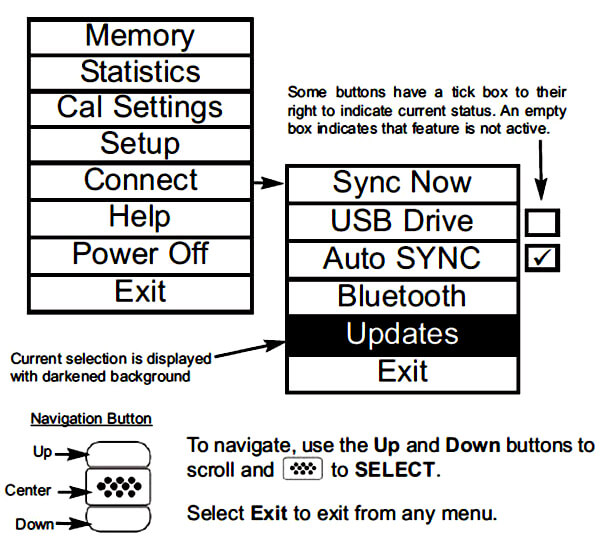
Cal Lock ![]()
When checked, the![]() icon appears and the current Cal settings are “locked” to prevent further user adjustments. Uncheck to make further adjustmentsnt range.
icon appears and the current Cal settings are “locked” to prevent further user adjustments. Uncheck to make further adjustmentsnt range.
Reset
Reset (menu Reset) restores factory settings and returns the Gage to a known condition. The following occurs:
- All batches, stored measurements, batch names and screen captures are erased.
- All calibration adjustments are cleared and returned to the Gage’s factory calibrationsettings.
- Menu settings are returned to the following:
|
Memory = OFF
Statistics Mode = OFF Hi Lo Alarm = OFF Min Scan = OFF |
A Scan = OFF
B Scan = OFF Cal Lock = OFF Bluetooth = OFF |
Display = None SE Mode = OFF Smart Couple = OFF |
Perform a more thorough Hard Reset by powering down the instrument, waiting several seconds, then simultaneously holding both the center![]() and (+) buttons until the Reset symbol
and (+) buttons until the Reset symbol![]() appears.
appears.
This returns the instrument to a known, “out-of-the-box” condition. It performs the same function as a menu Reset with the addition of:
- Bluetooth Pairing info is cleared
- Menu settings are returned to the following status:
| Units = millimeter
Flip Display = Normal Suto Sync = OFF White on Black = ON Language = English |
Battery Type = Alkaline
Backlight = Normal Bluetooth Streaming = OFF USB Drive = ON |
NOTE: Date, Time and WiFi settings are not affected by either Reset.
Gage Info
Displays the model number & serial number, probe type & serial number, PosiSoft.net registration key, the amount of remaining memory for storage of readings, date and time, and software packages.
For security purposes, the registration key is required to add the instrument to your free PosiSoft.net account.
Min Scan ![]()
Normally, the DeFelsko PosiTector UTG C takes a single spot measurement at a rate of 6 readings per second while in contact with a surface. When the probe is lifted, the minimum reading thickness will remain on the display.
It is sometimes necessary to examine a larger region to locate the thinnest point. When Min?Scan is selected, the DeFelsko PosiTector UTG C will measure at a rate of 20 readings per second and display min/max values.
The DeFelsko PosiTector UTG M measures at a rate of 4 readings per second when Min?Scan is selected.
During scanning operations, the probe can be become physically decoupled, that is physically separated, from the material, either due to the rough and/or scaly surface of the material or due to user operation. Avoid this by using the Smart Couple™ feature.
A Scan![]() (Advanced models only)
(Advanced models only)
| A display in which the received pulse amplitude is represented along y axis and the travel distance of the ultrasonic pulse is represented along the x axis.
|
 |
A Scan Menu ![]()
Use the Up (move left) and Down (move right) buttons to navigate.
Adjust Display Gain - Adjusts the A-Scan amplitude/sensitivity. Use the (-)(+) buttons to decrease/increase gain. Adjust Display Lo/Hi Range - Adjusts the minimum and maximum displayed range for the A-Scan. Use the(-)(+) buttons to decrease/increase gain. |
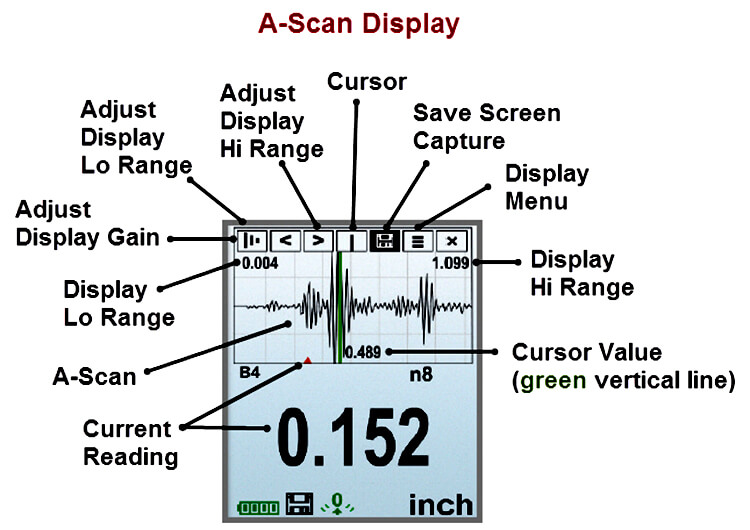 |
Note:?This does not change the instruments measuring range.
Move Cursor - The Cursor allows for further analysis of the A-Scan. Use the (-)(+) buttons to move the cursor along the A-Scan.
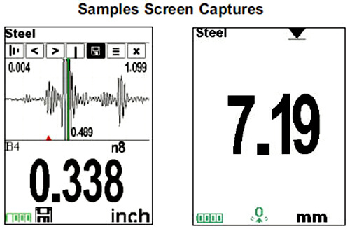
Save Screen Capture - Press![]() to capture and save an image copy of the current display. The last 10 screen captures are stored in memory and can be accessed when connected to a computer via?USB?Drive.
to capture and save an image copy of the current display. The last 10 screen captures are stored in memory and can be accessed when connected to a computer via?USB?Drive.
Display Menu - Press![]() to display the Gage menu
to display the Gage menu
Exit - Press![]() to close the A-Scan display. ?Press the Up button to return to the A-Scan display.
to close the A-Scan display. ?Press the Up button to return to the A-Scan display.
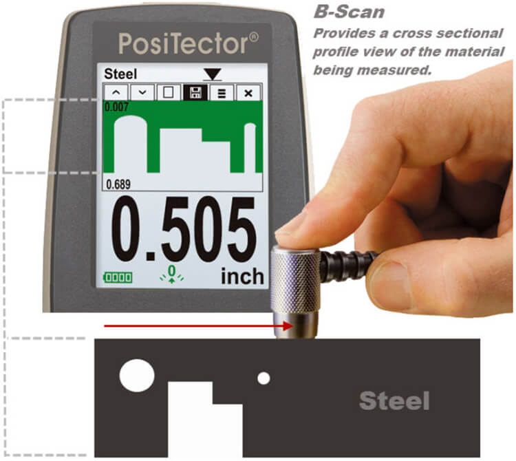
B Scan![]() (Advanced models only)
(Advanced models only)
A display in which a cross sectional profile of the test material is represented. |
 |
B Scan Menu ![]()
Use the Up (move left) and Down (move right) buttons to navigate.
Adjust Display Lo/Hi Range - Adjusts the minimum and maximum displayed range for the B-Scan. Use the (-)(+) buttons to decrease/increase gain. Note:?This does not alter the instruments measuring range. Clear Display - Press |
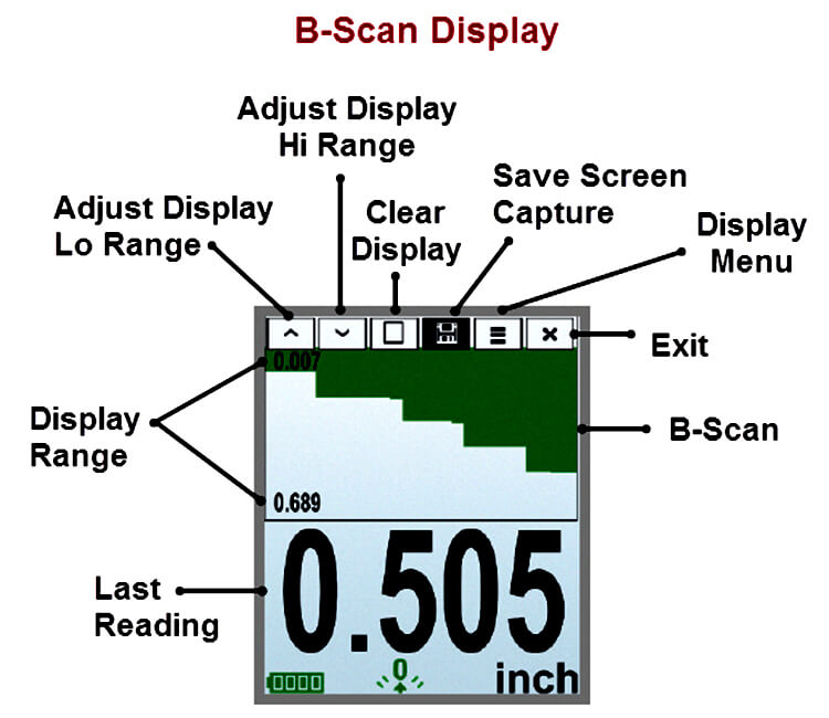 |
Display Menu - Press![]() to display the Gage menu
to display the Gage menu
Exit - Press![]() to close the B-Scan display. ?Press the Up button to return to the B-Scan display.
to close the B-Scan display. ?Press the Up button to return to the B-Scan display.
SE Mode![]() (UTG M multiple-echo probes only)
(UTG M multiple-echo probes only)
Switches from multiple-echo![]()
![]() to single-echo
to single-echo![]() mode:
mode:
- To detect pits and flaws
- To increase the measurement range
- To obtain thickness measurements in circumstances where multiple-echo can not
Smart Couple![]()
During scanning operations, the probe can be become physically decoupled, that is physically separated from the material, either due to the rough and/or scaly surface of the material or due to user operation.
When this happens, analysis of the material stops and statistics are displayed for only that portion of the surface to which the probe was coupled. If the probe re-couples on purpose or accidently, statistical values are reset to zero, and a new measurement analysis session begins.
Due to the physical decoupling of the probe, the Gage may output two or more independent measurement sessions. If the intention was to measure the maximum and minimum thicknesses continuously, erroneous indications may result due to the physical decoupling of the probe from the material.
Smart Couple™ mode maintains a continuous measurement session regardless of whether the probe becomes physically decoupled from the material, and analyzes the thickness values of the material at all locations where the probe was coupled.
This mode of operation provides a number of advantages. For example, the user can make multiple passes between various points of a material to be measured, and not have to actively concentrate on ensuring that the probe is physically coupled to the material. The user can therefore focus on the material itself, rather than the instrument, or can focus more closely on the measurement results displayed on the display. In addition, it provides higher accuracy and faster scanning, since the user does not have to stop and record between different scanning operations. The user can deliberately lift the probe and scan a new area knowing that all results will be analyzed if it were from one continuous scan.
Flip Display
This option causes the display to read upside down. Ideal for use overhead with the resultant display conveniently pointed toward the operator.
White on Black (Advanced models only)
Inverts the LCD display to white on a black background to provide better readability in some surroundings.
Backlight (Advanced models only)
Selects display brightness (Sun, Normal or Night). All settings will dim slightly after a period of no activity to conserve battery life. Press the Down button to brighten the display.
Set Clock
All measurements are date and time stamped (24 hour format) when stored into memory. It is therefore important to keep both the date and time current using this menu option. Use the Up and Down buttons to scroll, and the (-) and (+) buttons to adjust a value. The instrument’s date and time can also be viewed in Gage Info.
Battery Type
Selects the type of batteries used in the instrument from a choice of “Alkaline”, “Lithium” or “NiMH” (Nickel-metal hydride rechargeable). If NiMH is selected, the instrument will trickle charge the batteries while connected via USB to a PC or optional AC charger (Gage must be powered ON). The battery state indicator icon is calibrated for the selected battery type. No damage will occur if the wrong battery type is selected.
DeFelsko recommends eneloop (NiMH) rechargeable batteries.
Units
Converts the display from inch to metric or vice versa. Stored measurements in memory are not converted.
Note: Switching units will turn off Statistics, HiLo Alarm, and closes Memory.
Language
Converts displayed and printed words to the selected language.
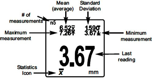
![]() Statistics Mode
Statistics Mode![]()
Statistics A statistical summarywill appear on the display. Remove the last measurement by pressing the (-) button. Press (+) to clear statistics. |
 |
HiLo Alarm ![]()
![]()
Allows the Gage to visibly and audibly alert the user when measurements exceed user-specified limits.
When HiLo Alarm is selected, the current Lo setting is displayed. Adjust down (-) or up (+). Alternatively, measure a coating with a thickness close to the required value and make final adjustments with the buttons. Select NEXT to accept this value. The current Hi setting is now displayed. Follow the same procedure to adjust the Hi setting.
The![]() icon will appear on the display.
icon will appear on the display.
Measurements will be compared to your defined HiLo limits. The Gage beeps if results are within those limits. A single low tone will sound if the reading is below the Lo limit, and a high tone if it is above the Hi limit. Press (+) to clear HiLo readings.
Clear
Clears all onscreen Statistics amd HiLo tabulations.
![]() Memory Management
Memory Management![]()
The PosiTector UTG can record readings in memory for printing to the optional Bluetooth wireless printer, transferring to a computer or synchronizing with PosiSoft.net. Readings are date and time-stamped as they are taken. Button functions with Memory on: |
 |
Standard models: Store up to 250 readings in one batch.
The following appears within the Memory menu:
- On: turns memory on and begins recording
- Off: stops recording (stored readings remain in memory)
- Clear: removes all readings from memory
- View: lists group statistics and all stored readings on the display. It will begin by showing statistics based on all readings in memory. Use the Up and Down buttons to scroll through all readings. Pressto exit.
Advanced models: Store 100,000 readings in up to 1,000 batches (groups).
The following appears within the Memory menu:
New Batch
Closes any currently opened batch and creates a new batch name using the lowest available number. For example, if only Batch 1 and Batch 3 exist, then Batch 2 would be created and made the current batch. The![]() icon appears and basic statistics are displayed. Each measurement will be displayed and stored into this new batch. On screen statistics are immediately updated with each measurement. New batch names are date stamped at the time they are created.
icon appears and basic statistics are displayed. Each measurement will be displayed and stored into this new batch. On screen statistics are immediately updated with each measurement. New batch names are date stamped at the time they are created.
Shortcut: When a batch is open, press (+) to create a new batch
Notes:
Remove the last reading from the current open batch by pressing (-).
Calibration adjustments cannot be made if readings are stored in memory.
If memory is ON while continuous measurements are being taken, only the last value on the display (when the probe is lifted) is stored into memory. Min Scan stores ALL measurements into memory.
New Sub-Batch: (appears only if a batch is currently open)
Creates a new sub-batch within the currently opened batch.
Shortcut: When a sub-batch is open, create a new sub-batch by pressing (+)
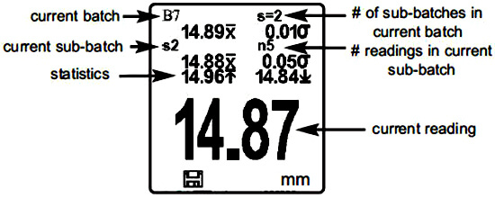
In the following example, B7s2 is a sub-batch of Batch 7. Subbatching allows the user to group related batches so that statistics can be accumulated for them. Batch 7 contains the statistics for B7s1 and B7s2. |
 |
Open
Selects a previously created batch or sub-batch name to open and make current. If it contains measurements, onscreen statistics will immediately reflect values calculated from this batch.
Note: A solid triangle is displayed to the right of the batch name when sub-batches are present. Press![]() to view sub- batches. This also applies to the Delete, View and Print options.
to view sub- batches. This also applies to the Delete, View and Print options.
Close
Stops the recording process, closes the current batch and removes the statistics from the display.
Delete
Removes a batch or sub-batch completely from memory. The name is deleted and all measurements are erased. Sub-batches can be deleted individually.
To delete all related sub-batches, simply delete the top-level batch.
View
Scroll using the Up or Down buttons through information, statistical summary, and a list of each reading in the currently opened batch.
Annotate: (Advanced models only)
Create meaningful batch names and enter notes directly on the instrument using a familiar onscreen QWERTY keyboard.
Use the Gages navigation and (-) (+) buttons to enter annotations.
Annotations can be synchronized with PosiSoft.net and are included in USB Mass Storage reports.
Print: (Advanced models only)
Sends a statistical summary and individual measurements to the optional Bluetooth wireless printer.
NOTE: To cancel printing, press and hold the (-) and (+) buttons simultaneously
Display: (appears only if a batch is currently open)
The following user selectable display options are available:
- Chart: A real-time x-y chart of batch or sub-batch readings.
- Image: An image uploaded (synchronized) from PosiSoft.net.
- Notes: Instructions or notes uploaded from PosiSoft.net.
- None: Default screen showing statistics information when a batch is open.
- Shortcut: When a batch is open, press Up to scroll through the above display options.
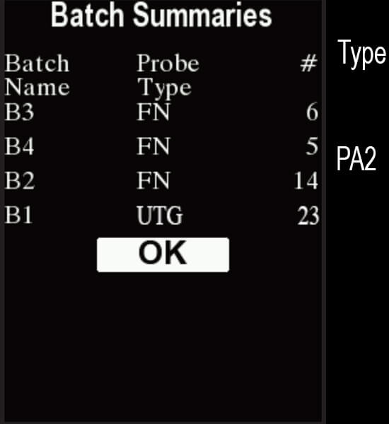
Summaries: (Advanced models only)
Screen Capture
![]() Connecting to a Computer
Connecting to a Computer![]()
The PosiTector can be connected to a computer using the included USB cable or Bluetooth wireless technology...
The USB connection has the following capabilities:
- Download readings via PosiSoft USB Drive
- Download readings and batch notes to PosiSoft software solutions
- Update the instrument firmware
- Supply power to the instrument for extended use, or recharge optional rechargeable batteries
The USB port resides on the top of the instrument, behind a rubber flap. |
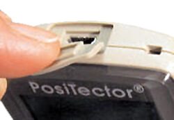 |
PosiSoft.net
To enhance the operation of your Gage, all PosiTector users have access to the features provided by PosiSoft.net. It is a web- based application offering secure centralized management of readings.
After (1) a user account has been created, (2) a Gage has been registered, and (3) the PosiSoft Desktop is downloaded and installed onto a Windows PC, synchronization of measurement data can be performed either manually or automatically whenever the PosiTector is connected to a web enabled PC by either USB cable or Bluetooth wireless technology. Gage measurements stored in memory are uploaded; images and batch notes are downloaded.
Uploaded data can be manipulated using a standard internet web browser from any location in the world - job site or head office. Reports and graphs with annotations and corporate logo can be generated. Data can be exported to XML or CSV (comma delimited) text files.
Measurement data can be shared with authorized users via a secure login from any computer and most web enabled devices including smart phones.
Register your Gage on PosiSoft.net to take full advantage of your gage’s capabilities. See www.PosiSoft.net
NOTE: A PosiSoft.net account is not required to Update your PosiTector. Simply download and install PosiSoft Desktop at www.defelsko.com.
![]() Outputting Stored Measurements
Outputting Stored Measurements![]()
Stored readings can be accessed using one of the following:
USB mass storage - connect your PosiTector to a PC/Mac using the suppled USB?cable to access and print stored readings and graphs. No software or internet connection required.
PosiSoft.net - a web-based application offering secure centralized storage of thickness readings. Access your readings from any web connected device. (See www.PosiSoft.net and Sync Now)
Bluetooth Printer (sold separately) - Stream readings as they are taken or print stored measurements including a statistical summaries (Advanced models only).
Legacy PosiSoft Support - Existing PosiSoft users can continue using the familiar legacy PosiSoft software to download readings. Upgrade your PosiSoft version at: www.DeFelsko.com/PosiSoft
Wifi: (Advanced models only) Allows connection to your local wireless network or mobile hot spot. Ideal for using your network’s internet connection for synchronizing stored measurements with PosiSoft.net. See www.defelsko.com/wifi |
 |
Enabled ![]()
Turns WiFi functionality ON. When selected, the icon will appear on the![]() display. To deactivate WiFi, uncheck the Enabled box.
display. To deactivate WiFi, uncheck the Enabled box.
Access Point ![]()
Connect your smart device/computer to a PosiTector Advanced body wirelessly without the need for a separate network. Wirelessly import readings into legacy PosiSoft 3.0 Desktop Software or whenever a WiFi network is not available or out-of-range.
To enable, select Access Point from the Connect > WiFi menu. The Access Point icon![]() will display in the upper left of the PosiTector display.
will display in the upper left of the PosiTector display.
Securing your Access Point -
To ensure the PosiTector is only accessible to authorized devices, it is important that you enter a passphrase (password) for the Access Point. The default Passphrase is password.
In the Connect > WiFi > Setup menu, select AP Passphrase.
Press![]() button to display on-screen keyboard. Enter a Passphrase for the Access Point. The Passphrase will be required for all devices connecting to the PosiTectors Access Point.
button to display on-screen keyboard. Enter a Passphrase for the Access Point. The Passphrase will be required for all devices connecting to the PosiTectors Access Point.
The PosiTector is now visible to all WiFi enabled devices. Simply connect your devices WiFi to the new PosiTector Access point. All PosiTectors are uniquely identified by their respective gage body serial numbers.
AP Channel - Default Channel: 6
For most users the default channel will not have to be altered. If you are experiencing poor connection or are unable to connect, try another channel.
In the Connect > WiFi > Setup menu, select AP Channel.
Press the UP center navigation button to highlight the channel. Use the (-) or (+) buttons to change the channel. Press the DOWN navigation button and select OK. Press![]() the button.
the button.
Networks
With WiFi Enabled the Gage will allow the user to add a new network and will automatically check for available local networks. Available networks detected by the Gage are listed on the screen along with any networks that the Gage has previously been connected to that are not currently within connection range.
Information
Gage displays information about the local WiFi network connection including...
- SSID: the network’s name
- State: displays if the Gage is connected to the network or not
- IP Address: the network’s IP Address. Users can enter this number into a web-browser of any WiFi enabled device that is connected to the same network in order to view the Gage’s synced batches.
Setup
Allows user to setup a WiFi connection
- IP Settings: enter the IP information as follows: IP Type (DHCP or Static), IP Address, Gateway, Netmask, DNS1, DNS2
- Server Enable: enables a connection between the network and the Gage.
- Gage Name: enter a name for the Gage (up to 14 Characters).
- AP Channel: (Default Channel: 6) The access point channel corresponding to a frequency range.
- AP Passphrase: (Default Passphrase: password) A series of characters, numbers or symbols used to log on to a WiFi network.
- WiFi Reset: erases all WiFi settings.
USB
When USB Drive is checked![]() , the PosiTector gage uses a USB mass storage device class which provides users with a simple interface to retrieve stored data in a manner similar to USB flash drives, digital cameras and digital audio players.
, the PosiTector gage uses a USB mass storage device class which provides users with a simple interface to retrieve stored data in a manner similar to USB flash drives, digital cameras and digital audio players.
USB Drive is also required to import stored measurements into PosiSoft Desktop software. Once connected, any computer can view measurements stored in memory by navigating a virtual drive labeled "PosiTector” using the included USB cable.
A formatted HTML report is viewed by selecting the "index.html" or “START_HERE.html” file found in the root directory. Optionally, text ".txt" files located in each batch folder provide access to measurement values. Stored datasets and graphs can be viewed or copied using universal PC/Mac web browsers or file explorers.
When your PosiTector is first connected to your Windows PC via a USB cable, an enumeration process is started that installs device drivers without re-booting your computer. You may see several pop-up windows in the taskbar at the bottom right of your screen. Wait for the entire process to be completed before proceeding.
Retrieving stored screen captures:
The last 10 screen captures stored in memory can be accessed by navigating to the “screen capture” directory within the “PosiTector” virtual drive.
NOTE: When connected, power is supplied through the USB cable. The batteries are not used and the body will not automatically power down. If rechargeable (NiMH) batteries are installed, the instrument will trickle charge the batteries.
Sync.net Now
The WiFi, USB and Bluetooth menus contain a Sync .net Now option. When selected, the Gage immediately synchronizes stored measurement data via its respective communication method (internet connection required).
Alternatively, select Auto Sync .net from within the USB connect menu to automatically synchronize upon connection to a PC. Additional measurements added to memory while connected are synchronized only when the USB cable is disconnected and reconnected, or when the Sync .net Now option is selected.
WiFi connected gages automatically attempt synchronization upon power-up.
NOTE: PosiSoft Desktop is required when using USB connections to synchronize measurements with PosiSoft.net.
Bluetooth Smart (Advanced models only, serial numbers 784000 and greater) When Enabled |
Select![]() batches to flag them for synchronization to the PosiTector App. New batches created while Bluetooth Smart is enabled are automatically selected.
batches to flag them for synchronization to the PosiTector App. New batches created while Bluetooth Smart is enabled are automatically selected.
Sync Batches
With Bluetooth Smart enabled, select Sync Batches to transfer selected![]() batches to the PosiTector App. This is useful when switching between smart devices, as only readings and batches that have yet to be synchronized with any smart device are synchronized automatically.
batches to the PosiTector App. This is useful when switching between smart devices, as only readings and batches that have yet to be synchronized with any smart device are synchronized automatically.
NOTE: If Bluetooth Smart is disabled, data from batches selected in the Sync Batches menu are held in a queue until communication with the PosiTector App is re-established.
Send Batches
Transfers selected![]() batches to the PosiTector App (useful when switching between devices).
batches to the PosiTector App (useful when switching between devices).
The Send Batches option is visible in the Bluetooth Smart menu when the Gage is connected to a smart device running the PosiTector App.
Bluetooth Smart (Advanced models only) Allows individual readings to be sent to a computer, printer or compatible device as they are taken using Bluetooth wireless technology. See www.defelsko.com/bluetooth |
- PosiTector Advanced models have Bluetooth functionality to:
- Communicate with PosiTector App in lieu of a USB cable.
- Stream individual readings to a computer or Bluetooth wireless printer as they are taken.
- Print to the optional battery powered Bluetooth wireless printer.
Enabled![]() : Turns Bluetooth functionality ON. When selected, the
: Turns Bluetooth functionality ON. When selected, the![]() icon will appear on the display. To deactivate Bluetooth, uncheck the Enabled box.
icon will appear on the display. To deactivate Bluetooth, uncheck the Enabled box.
Pairing: The instrument and receiving device must be paired before stored or streamed datasets can be transmitted. For pairing instructions, see http://www.defelsko.com/bluetooth
Info: Lists information about your current Bluetooth connection, including the currently paired device and MAC address..
Stream: When checked, the instrument will stream datasets to the paired Bluetooth Device as they are taken. Datasets can be streamed as they are taken to the optional Bluetooth printer or third-party computer software.
Powder Probes: Displays menu options that enable the PosiTector body to communicate with wireless PosiTector PC probes. See http://www.defelsko.com/pc
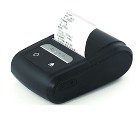
Bluetooth Wireless Printer
PosiTector Advanced models can output to the optional battery powered Bluetooth wireless printer one of two ways:
Begin by entering the Connect > Bluetooth menu. Turn Bluetooth ON and “Pair” the PosiTector to the printer. See: www.defelsko.com/bluetooth/ |
 |
Streaming: In the Connect > Bluetooth menu, select the “Stream” tick box. All readings will now be simultaneously displayed on the LCD and sent to the printer.
Printing: In the Memory menu, select Print.
Updates
Determine if a software update is available for your Gage. See www.defelsko.com/update To perform an update the Gage must be connected to an internet connected PC with PosiSoft Desktop or WiFi network. |
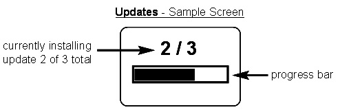 |
WARNING: Ensure that stored measurements are backed up to a PC or PosiSoft.net.
The Gage will perform a Hard Reset after an update. All stored measurements will be erased from memory.
![]() Do Not unplug the Gage during the update operation.
Do Not unplug the Gage during the update operation.
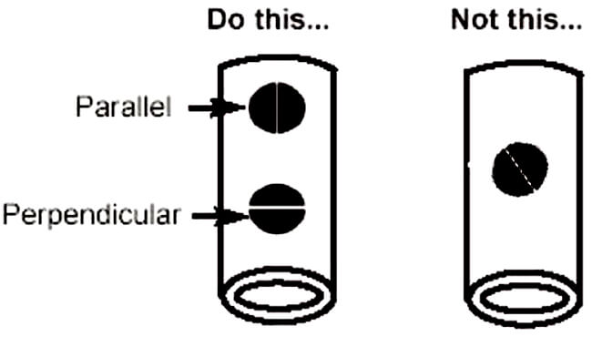
Measuring on Pipes (UTG C probes)
When measuring the thickness of pipe walls, the proper placement of the transducer is important. On pipe diameters larger than 10cm (4 inches), it is recommended to place the probe parallel to the long axis of the pipe. For smaller diameter pipes, it is recommended that two measurements be taken, one with the probe perpendicular, and another with the probe parallel to the long axis of the pipe. The smaller of the two measurements should be recorded as the thickness for that area.
 |
Measuring on rough surfaces
To optimize measurement results, the surface should first be cleaned of any foreign debris including rust and scale. Depending on the amount of contamination/ roughness, abrasion with a wire brush or grinding tool may be necessary.
On rough surfaces, the use of a generous amount of couplant minimizes the surface effects and serves to protect wear on the transducer, particularly when dragging across the surface is involved.
During scanning operations, the probe can be become physically decoupled, that is physically separated, from the material, either due to the rough and/or scaly surface of the material or due to user operation. Avoid this by using the Smart Couple™ feature.
Measuring on hot surfaces
Measurements taken at higher temperatures (above 100° C / 212° F) require special consideration. Both material sound velocity and probe zero will change with temperature. For maximum accuracy at high temperatures, adjustment should be performed using a material of known thickness heated to the temperature where measurements are to be performed. The probe should remain on the surface only as long as it takes to get a measurement.
The surface temperature of the test piece should not exceed (150° C / 300° F).
Measuring laminated materials
The density (and thus sound velocity) of laminated materials often varies considerably within a single piece or from piece to piece. For best accuracy, perform a calibration adjustment to a sample of known thickness. This sample should be as close as possible to the density characteristics of the part to be measured. Be aware that air gaps between laminates will likely cause strong reflections, resulting in the Gage measuring a lower thickness value than the actual total thickness.
Calibration
Measurement accuracy is directly related to the accuracy and care taken when performing a gage calibration adjustment. Adjustments will likely be required whenever the test material or temperature changes. Periodic checks with samples of known thickness are recommended to verify that the Gage is operating properly.
Taper or Eccentricity
If the measured surface and the back wall are not parallel to one another, measurement accuracy may be diminished due to a distorted echo.
Sound Scattering
Some materials have conditions which can limit the accuracy and thickness range of the Gage. For example, individual crystallites in cast metals and dissimilar materials in composites can scatter the ultrasonic pulse. The return echo may be too weak for the Gage to effect a measurement.
![]() Troubleshooting - General
Troubleshooting - General![]()
Some common reports received by our Service Department along with possible causes. Most conditions however can be cleared with a Reset.
Gage fails to power down
Ensure the probe is clean and free of couplant. The Gage will not turn off if coupled symbol![]() is displayed on LCD.
is displayed on LCD.
Probe measures when lifted from surface
Wipe away any excess couplant on probe tip.
Gage readings double expected thickness
This sometimes occurs near the minimum measuring range of the instrument. The first return echo is unmeasurable, so the Gage measures the second return echo. The resultant calculation is double the actual thickness.
Measurement jumps when probe is lifted
Occasionally, excess couplant will remain on the probe when the probe is lifted from the surface. This may cause the DeFelsko PosiTector UTG to display a final measurement value different from those observed when the probe was on the surface. Discard this value and repeat the measurement.
UTG M multiple echo (ME) probes only
Gage is coupled, but not measuring
On smooth, uncoated metal surfaces the Gage (in multiple echo (ME) mode) may occasionally be unable to give a measurement result even when the "coupled" symbol appears. Use additional couplant and lighter pressure on the probe when measuring. Switching the Gage to SE mode will also help pro- duce a steel-only thickness measurement. Alternatively, laying a plastic shim on the surface with couplant applied to both sides to simulate a painted surface will help produce a steel-only thickness measurement in ME mode.
When measuring non-parallel surfaces, ME mode does not display a reading
Measurement accuracy may be diminished when ME mode is used to measure a part that has non-parallel surface and back walls. A distorted echo or no echo at all may result. Switch to SE mode and retry.
Thickness values are repeatable, but seem incorrect
- When measuring thick, hard coatings on thin metal, ME and SE modes may both give improper results. This unusual condition results in many gages interpreting the thick coating as the metal and the thin metal as a coating on the backside. The Gage therefore displays the thickness of the coating using the velocity calibration for the metal. This application may not be measurable.
- OR
- The Cal?Settings property may be incorrect. For best accuracy the Gage must be set to the correct sound velocity for that material.
- OR
- Too much loose rust or scale may be present on the surface. Scrape away loose material with a wire brush or scaper and apply sufficient couplant. In extreme cases, rotary sanders or grinding wheels may be necessary using care not to gouge the surface.
- OR
- There may be a coating on both sides of the metal. Switch to SE mode for best results.
ME (multiple echo) and SE (single echo) results are not the same
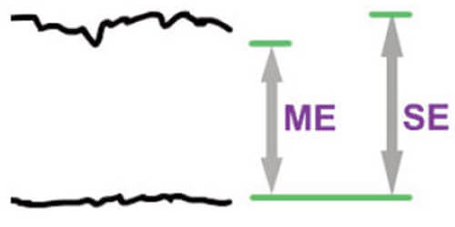
When measuring a COATED piece of metal, ME and SE modes will likely produce different thickness values as expected. The ME value will be thinner since it represents the thickness of only the metal (ignores the coating).
Measurements of an UNCOATED piece of metal, however, should be the same (within tolerance) except in the following circumstances.
Surface Roughness, scale, etc. ME mode may produce thinner measurement results because it may ignore the surface roughness in much the same way it ignores coatings. |
 |
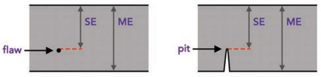
Flaws, voids or pits
A void or flaw inside a metal object is better detected in SE mode where the Gage will measure the distance from the surface down to the flaw. Scan-mode will help locate the flaw. In ME mode the Gage may not “see” the flaw and will display a thicker, total thickness value. |
 |
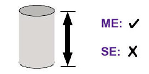
Measuring the depth of a rod ME mode may produce accurate results in situations where SE mode may not be able to measure at all. |
 |
Probe pressure
Applying too much hand pressure on the probe while measuring may squeeze out too much couplant and make it difficult for ME mode to effect a measurement.
Temperature
Probe temperature: ME values are not affected by temperature changes within the probe. But the Gage should be zeroed for best accuracy when operated in SE mode.
Metal temperature: Sound waves travel faster when the material is heated. Preprogrammed sound velocities within the PosiTector UTG are valid for normal temperatures in the vicinity of 15°C and must be adjusted for extreme temperatures. For best results in either mode, the Gage should be adjusted to the known thickness of the material at a temperature similar to the part being measured.
![]() Power Supply / Battery Indicator
Power Supply / Battery Indicator![]()
Power Source: 3 AAA?alkaline, Lithium or optional Nickel-metal hydride (NiMH) rechargeable batteries. For best battery indicator results, ensure the appropriate Battery Type is selected in the Setup > Battery Type menu.
The battery indicator![]() displays a full bar with fresh alkaline or fully charged batteries installed. As the batteries weaken, the bar will be reduced. When the battery symbol is low
displays a full bar with fresh alkaline or fully charged batteries installed. As the batteries weaken, the bar will be reduced. When the battery symbol is low![]() the Gage can still be used, but the batteries should be changed or recharged at the earliest opportunity. The Gage will turn off automatically when batteries are very low, preceded by a Low Battery Warning on the display.
the Gage can still be used, but the batteries should be changed or recharged at the earliest opportunity. The Gage will turn off automatically when batteries are very low, preceded by a Low Battery Warning on the display.
![]() To retain all user settings and stored memory readings, only replace the batteries after the instrument has powered-down. Battery performance decreases at low temperatures.
To retain all user settings and stored memory readings, only replace the batteries after the instrument has powered-down. Battery performance decreases at low temperatures.
Rechargeable Batteries (available option)
DeFelsko recommends the use of eneloop (NiMH) rechargeable batteries. They combine the advantages of rechargeable batteries and disposable (Alkaline) batteries. They discharge very slowly and can be stored for long periods without having self discharge concerns. (See www.eneloop.info).
![]() Technical Data
Technical Data![]()
Operating Range
Gage: 0 to 50° C (+32° to +120° F) |
 |
Size: 146 x 61 x 28 mm (5.75” x 2.4” x 1.1”)
Weight: 140 g (4.9 oz.) without batteries
Conforms to: ASTM E797
This device complies with part 15 of the FCC Rules. Operation is subject to the following two conditions: (1) This device may not cause harmful interfer- ence, and (2) this device must accept any interference received, including interference that may cause undesired operation.
![]() Returning for Service
Returning for Service![]()
Before returning the instrument for service.
- Install new or newly recharged batteries in the proper alignment as shown within battery compartment.
- Examine the probe tip for dirt or damage.
- Perform a Hard Reset and a Zero.
IMPORTANT: If you must return the Gage for service, please fill out and include the Service Form located at www.defelsko.com/support with the instrument.
![]() Limited Warranty, Sole Remedy and Limited Liability
Limited Warranty, Sole Remedy and Limited Liability![]()
DeFelsko's sole warranty, remedy, and liability are the express limited warranty, remedy, and limited liability that are set forth on its website: www.defelsko.com/terms
This manual is copyrighted with all rights reserved and may not be reproduced or transmitted, in whole or part, by any means, without written permission from DeFelsko Corporation.
DeFelsko and PosiTector are trademarks of DeFelsko Corporation registered in the U.S. and in other countries. Other brand or product names are trademarks or registered trademarks of their respective holders.
Every effort has been made to ensure that the information in this manual is accurate. DeFelsko is not responsible for printing or clerical errors.
![]()