DeFelsko PosiTector 200 Instruction Manual
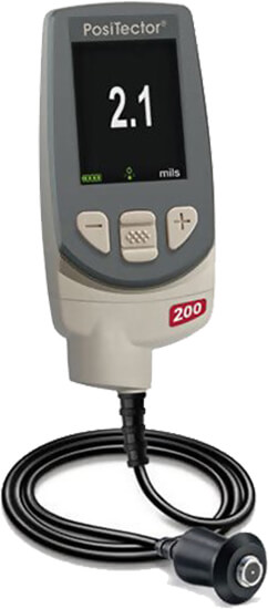
The PosiTector 200 is a hand-held Coating Thickness Gage that uses a non-destructive ultrasonic principle to measure coating thickness on a wide variety of substrates. It consists of a body (Standard or Advanced) and a probe.
PosiTector 200 Kit Contents
- PosiTector body (Standard or Advanced)
- PosiTector probe (200 B, C or D)
- Protective rubber cap for Probe
- Protective lens shield
- Wrist strap
- 3 AAA batteries
- Quick Guide instruction booklet
- Protective rubber holster
- Nylon carrying case with shoulder strap
- Belt clip for rubber holster and carrying case
- USB Cable
- 4 ounce (118 ml) bottle ultrasonic couplant
- Precision Plastic Shims (B Probe only)
- 2500 microns (100 mils) Polystyrene Block (C & D Probe only)
- Certificate of Calibration traceable to NIST or PTB
- PosiSoft.net account
- Two (2) year warranty on Body and Probe
The PosiTector 200 powers-up when the center navigation button![]() is pressed. To preserve battery life, the Gage powers down after approximately 5 minutes of no activity. All settings are retained.
is pressed. To preserve battery life, the Gage powers down after approximately 5 minutes of no activity. All settings are retained.
- Remove the protective rubber cap from the probe.
- Power-up the Gage by pressing the center navigation
 button.
 - Zero the probe.
- Adjust to a known thickness, if necessary.
- Measure the part.
Protective Cap
|
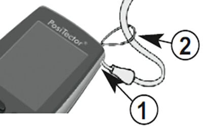
Wrist Strap
We recommend attaching and wearing the supplied wrist strap.
Plastic Lens Shield
The LCD is covered with a thin plastic film for protection against fingerprints and other marks during shipment. This film, while usually removed before using the Gage, can be left in place to protect against paint overspray or debris. Replacements can be purchased.
Couplant
Couplant is required to propagate ultrasound into the coating. Water is a good couplant for smooth coatings. Use the supplied glycol gel for rougher coatings. While it is unlikely that the couplant will damage the finish or leave a stain on the surface, we suggest testing the surface by using the couplant on a sample. If testing indicates that staining has occurred, a small amount of water can be used instead of couplant. Consult the Material Safety Data Sheet and your coating supplier if you suspect the couplant may damage the coating. Other liquids such as liquid soap may also be used.
All PosiTector 200 probes include a Certificate of Calibration. For organizations with re-certification requirements, instruments may be returned at regular intervals for calibration.
DeFelsko recommends that customers establish calibration intervals based upon their own experience and work environment. Based on our product knowledge, data and customer feedback, a one year calibration interval from either the date of calibration, date of purchase, or date of receipt is a typical starting point. |
 |
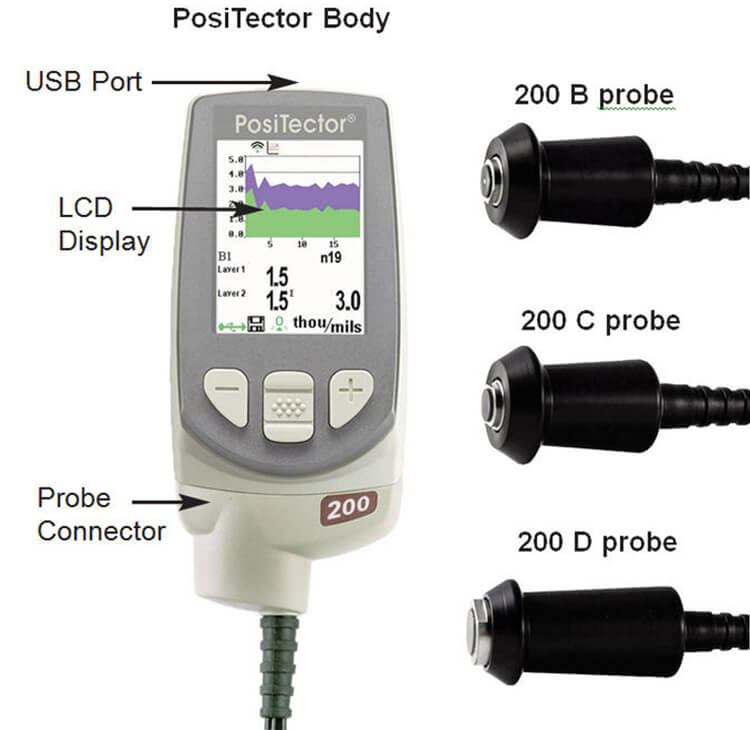
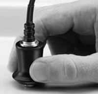
To disconnect a probe from a body, power-down the Gage and slide the plastic probe connector horizontally (in the direction of the arrow) away from the body. Reverse these steps to attach a new probe.
When powered-up the PosiTector automatically determines what type of probe is attached and does a self-check.
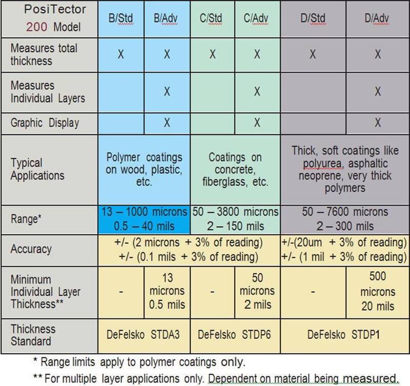
PosiTector 200 probes are available for measuring a wide variety of coating thickness applications.
- Probe: 13 to 1000 microns (0.5 to 40 mils) Ideal for polymer coatings on wood, plastic, composites, etc.
- Probe: 50 to 3800 microns (2 to 150 mils) Ideal for thicker coatings on concrete, fiberglass,etc.
- Probe: 50 to 7600 microns (2 to 300 mils) Ideal for thick, soft coatings such as asphaltic neoprene, very thick polymers, polyurea, etc. (50 to 5000 microns (2 to 200 mils) Polyurea measuring range)
NOTE: Range limits apply to polymer coatings only.
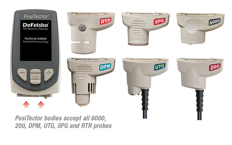
Additionally, the PosiTector accepts a number of probe types including magnetic and eddy current coating thickness, surface profile, environmental and ultrasonic wall thickness probes. Perform the latest software Updates to ensure probe compatibility with your Gage. For the latest information on probe interchangeability.
PosiTector body accepts all 200, 6000, SPG, RTR, DPM and UTG probes. . |
 |
![]() Ultrasonic Thickness Theory of Operation
Ultrasonic Thickness Theory of Operation![]()
The PosiTector 200 probe emits a high frequency sound pulse that travels into the coating via a coupling gel and reflects from ANY surface that is different in density.
Coating thickness readings are obtained by measuring the time taken for the ultrasonic signal to propagate from the probe to the coating/substrate interface and back. The travel time is divided by two and multiplied by the velocity of sound in the coating to obtain the thickness of the coating. |
 |
|
 |
- Lift the probe when you hear a double BEEP, - OR - leave probe on the surface in the same location for continuous measurements.
- When completely finished, wipe the probe clean of couplant then return the Gage to the protective pouch. There is no need to disconnect the probe from the PosiTector during storage.
![]() Calibration, Verification and Adjustment
Calibration, Verification and Adjustment![]()
Three steps ensure best accuracy...
- Calibration - typically done by the manufacturer.?All probes include a Certificate of Calibration.
- Verification of Accuracy - typically done by the user on known reference standards such as plastic shims or coated thickness standards.
- Adjustment - to a known thickness
Calibration
Calibration is the high-level, controlled and documented process of measuring traceable calibration standards over the full operating range of the probe, and verifying that the results are within the stated accuracy of the probe. Calibrations are performed by the manufacturer, their authorized agent, or by an accredited calibration laboratory in a controlled environment using a documented process.
Verification
Verification is an accuracy check performed by the user on known reference standards. A successful verification requires the Gage to read within the combined accuracy of the probe and the reference standards.
Adjustment
Adjustment, or Cal Adjustment, is the physical act of aligning the probe’s thickness readings to match those of a known thickness sample (removal of bias) in order to improve the accuracy of the probe on a specific coating. See Thickness
Gage functions are menu controlled. To access the Menu, pwoer-up the Gage, then press the center navigation button
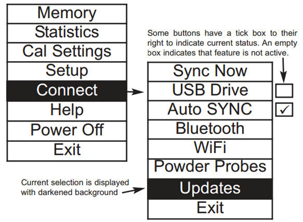
Below is a sample menu for a PosiTector 200 Advanced model: |
 |
NOTE:The center button is purposely recessed to help eliminate unintentional powering-up of the Gage. |
 |
Zero
PosiTector 200 probes must be periodically zeroed using the ZERO menu option to compensate for both extreme temperature and probe wear effects. Before using, allow the probe to reach ambient temperature. Theicon appears after a Cal Reset.
If measurements will be made in extreme hot or cold temperatures, it is recommended to ZERO the probe in the working environment. If measurements will be made on rough substrates, it is recommended to periodically ZERO the probe to compensate for wear.
- Make sure the Gage is on and the probe is wiped clean.
- Hold probe in air away from the substrate.
- Select the Zero menu option.
- When complete, Gage will double beep and display "----".
Set Range
The measuring range of each probe can be changed depending on the specific application or the expected thickness range of the coating system.
For most applications, the default range values do not have to be adjusted. But some conditions, like surface roughness, may cause the Gage to display very low or non-repeatable readings. In this case, the low range may be increased to cause the Gage to only display readings above the Lo value set by the user.
To adjust Set Range values.
- Selectorwith the Up and Down buttons.
- Use the (-) (+) buttons to decrease/increase the displayed value.
IMPORTANT:
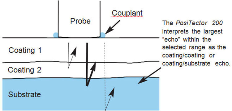
The PosiTector 200 interprets the largest “echo” or “echoes” within the selected range as the coating/coating or coating/substrate echo. If the coating thickness is outside this range, incorrect or dashed readings may occur.
Here are some typical Range settings.
| Expected paint thickness | Lo Range | Hi Range |
| 500µm (20 mils) on concrete | 130µm (5 mils) | 1000µm (40 mils) |
| 50µm (2 mils) on wood | 25µm (1 mil) | 250µm (10 mils) |
Thickness
The PosiTector 200 measures most polymer coatings accurately out-of-box with no adjustment required.
To determine if an adjustment is necessary, select a coating sample of known thickness as close as possible in composition to the intended application. For best results, the thickness of the sample should be equal to or slightly greater than the maximum expected thickness of the coating to be measured.
Measure the coated sample. If the average of a series of measurements on the sample is not close to the known thickness.
- Select the Thickness menu option.
- Use (-) or (+) to decrease/increase the displayed measurement thickness value to match the known thickness of the sample.
- For Advanced models with multiple layers selected, use the Down navigation button to select the next layer and adjust as necessary.
- To save adjustments, use Down navigation button to highlight OK and press the center navigationbutton.
Polyurea(PosiTector 200 D probes only)
When checked, the Gage loads a pre-programmed calibration adjustment optimized for measurement of polyurea coatings. “Polyurea” will appear on the upper right corner of the display.
NOTE: D Probe Measuring Range: 2 - 200 mils (50 - 5000 um)
Cal Lock
When checked, theicon appears and the current calibration settings are “locked” to prevent further user adjustments.
Cal Reset
Restores the Gage back to factory calibration and range settings. Theicon will appear on the display.
Reset
Reset (soft reset) restores factory settings and returns the instrument to a known condition. The following occurs:
- All batches, stored measurements, images, batch names and screen captures are erased.
- All calibration and range adjustments are cleared and returned to the Gage's factory settings.
- The icon will appear on the display.
- Menu settings are returned to the following:
| Memory = OFF | Graphics = ON | Layer Name = Layer 1 |
| Bluetooth = OFF | Display = None | Cal Lock = OFF |
| Layers = 1 | Layer Color = blue |
Perform a more thorough Hard Reset by powering down the Gage, waiting several seconds, then simultaneously holding both the center![]() and (+) buttons until the Reset symbol appears. This returns the instrument to a known, “out-of-the-box” condition. It performs the same function as a menu Reset with the addition of:
and (+) buttons until the Reset symbol appears. This returns the instrument to a known, “out-of-the-box” condition. It performs the same function as a menu Reset with the addition of:
- Bluetooth Pairing info is cleared
- Menu settings are returned to the following:
| Units = microns | Language = English | Battery Type = Alkaline | USB Drive = ON |
| Flip Display = Normal | Polyurea = OFF | Backlight = Normal | Auto Sync = OFF |
Note: Date, Time and WiFi settings are not affected by either Reset.
Gage Info
Displays the model number & serial number, probe type & serial number, PosiSoft.net registration key, the amount of remaining memory for storage of readings, date and time and software packages.
For security purposes, the registration key is required to add the Gage to your PosiSoft.net account.
Graphics(Advanced models only)
When selected, the Gage displays a graphical representation of the ultrasonic pulse as it travels through the coating system.
| As the probe is depressed and the ultrasonic pulse travels through the coating system, the pulse encounters changes in density at the interfaces between coating layers and between the coating and the substrate. |  |
These interfaces are depicted by a "peak". The greater the change in density, the higher the peak. The more gradual the change in density, the greater the width of the peak. For example, two coating layers made of essentially the same material and "blended" would result in a low, wide peak. Two materials of very different density and a well-defined interface would result in a high, narrow peak.
The PosiTector 200 chooses the highest peak (single layer) or peaks (multi-layer) within the Set Range. For example, if the number of layers is set to 3, the three highest peaks would be identified with small red triangles. The peak values are also displayed numerically as thickness measurements.
NOTE: The Graphics display can also be accessed using the Set Range menu option
![]()
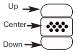
Use the navigation Up (move left) and Down (move right) buttons to highlight icons on the graphic display.
![]() Zoom - Visually magnifies the waveform of the displayed peaks for more visibility. Pressing the (-) or (+) button repeatedly will increase/decrease the zoom.
Zoom - Visually magnifies the waveform of the displayed peaks for more visibility. Pressing the (-) or (+) button repeatedly will increase/decrease the zoom.
![]()
![]() Set Range - Press the (-) or (+) buttons to adjust the Gage’s Lo or Hi measuring range.
Set Range - Press the (-) or (+) buttons to adjust the Gage’s Lo or Hi measuring range.
![]() Screen Capture - Press to capture and save an image copy of the current display. The last 10 screen captures are stored in memory and can be accessed when connected to a computer. See Screen Capture and PosiSoft USB Drive. SHORTCUT: Press and hold the (-)(+) buttons simultaneously to capture any screen.
Screen Capture - Press to capture and save an image copy of the current display. The last 10 screen captures are stored in memory and can be accessed when connected to a computer. See Screen Capture and PosiSoft USB Drive. SHORTCUT: Press and hold the (-)(+) buttons simultaneously to capture any screen.
![]() Menu - Press to access the Gage’s main menu.
Menu - Press to access the Gage’s main menu.
![]() Exit - Press to close the Graphics display. Press the Up button to return to the Graphics display.
Exit - Press to close the Graphics display. Press the Up button to return to the Graphics display.
Layers (Advanced models only)
| Advanced models of the PosiTector 200 are capable of numerically displaying up to three individual layer thicknesses in a multi-layer system. | 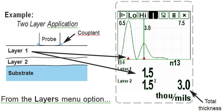 |
| Select up to three individual layer thickness values: | 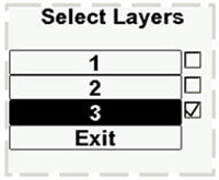 |
Edit:
|
|
NOTES: Before setting up the Gage for multi-layer measurement, it is recommended that you first take measurements in single layer mode and interpret the results using the Graphics option.
When a batch is Open, press the Up button to view the Batch Chart.
Flip Display
This option causes the display to read upside down. Ideal for use overhead with the resultant display conveniently pointed toward the operator.
Backlight
Selects display brightness (Sun, Normal or Night). All settings will dim slightly after a period of no activity to conserve battery life. Press the Down button to brighten the display.
Set Clock
All measurements are date and time stamped (24 hour format) when stored into memory. It is therefore important to keep both the date and time current using this menu option. Use the Up and Down buttons to scroll, and the (-) and (+) buttons to adjust a value. The instrument’s date and time can also be viewed in Gage Info
Battery Type
Selects the type of batteries used in the instrument from a choice of “Alkaline”, “Lithium” or “NiMH” (Nickel-metal hydride rechargeable). If NiMH is selected, the instrument will trickle charge the batteries while connected via USB to a PC or optional AC charger (Gage must be powered ON). The battery state indicator icon is calibrated for the selected battery type. No damage will occur if the wrong battery type is selected.
DeFelsko recommends eneloop (NiMH) rechargeable batteries.
Units
Converts the display from inch to metric or vice versa. Stored measurements in memory are not converted. Switching units will turn off Statistics view and closes Memory.
Language
Converts displayed and printed words to the selected language.
The PosiTector 6000 has internal memory storage for recording measurement data. Stored measurements can be reviewed on-screen or accessed via computers, tablets and smart phones. Measurements are date and time-stamped.
The ![]() symbol appears and basic statistics are displayed when the Gage is set to store measurement data.
symbol appears and basic statistics are displayed when the Gage is set to store measurement data.
| Button functions with Memory ON: | 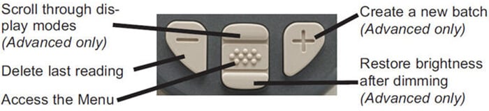 |
Standard models store up to 250 readings in one batch. The Memory Menu includes the following options...
- On: turns memory on and begins recording
- Off: stops recording (stored readings remain in memory)
- Clear: removes all readings from memory
- View: lists group statistics and all stored readings on the display. It will begin by showing statistics based on all readings in memory. Use the Up and Down buttons to scroll through all readings. Press to exit.
| Standard model display with Memory ON shows measurement statistics. | 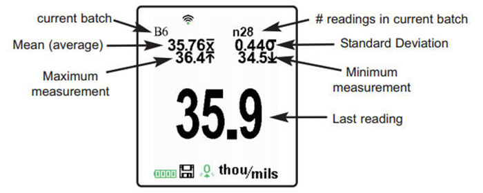 |
Advanced models store 100,000 readings in up to 1,000 batches. The Memory Menu include the following options
New Batch
Closes any currently opened batch and creates a new batch name using the lowest available number. For example, if only Batch 1 and Batch 3 exist, then Batch 2 would be created and made the current batch. Each measurement will be displayed and stored into this new batch. On screen statistics are immediately updated with each measurement. New batch names are date stamped at the time they are created.
| Shortcut: When a batch is open, press (+) to create a new batch | 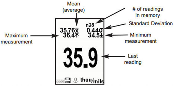 |
NOTES:
- Remove the last reading from the current open batch by pressing (-).
- Calibration adjustments cannot be made if readings are stored in memory.
New Sub-Batch
(appears only if a batch is currently open)
Creates a new sub-batch within the currently opened batch.
Shortcut: When a sub-batch is open, create a new sub-batch by pressing (+).
| In the following example, B2s2 is a sub-batch of Batch 2. | 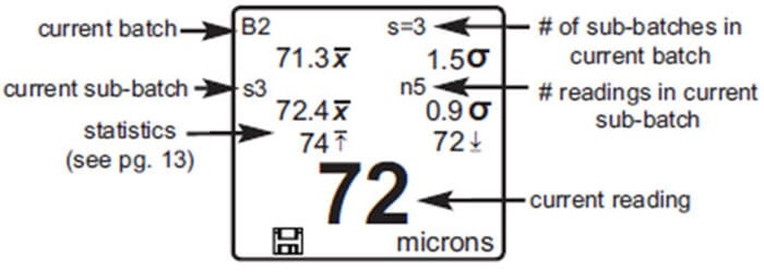 |
Sub-batching allows the user to group related batches so that statistics can be accumulated for them. Batch 2 contains the statistics for B2s1 and B2s2.
Helps determine if film thickness over a large area conforms to user specified min/max levels. See www.defelsko.com/pa2.
Determines if a coating system complies with the IMO performance standard for protective coatings. See www.defelsko.com/9010.
Open
Selects a previously created batch or sub-batch name to open and make current. If it contains measurements, on-screen statistics will immediately reflect values calculated from this batch. The calibration setting (i.e. Cal 2) associated with this batch is also opened.
NOTE: A solid triangle ![]() is displayed to the right of the batch name when sub-batches are present. Press
is displayed to the right of the batch name when sub-batches are present. Press ![]() to view subbatches. This also applies to the Delete, View and Print options.
to view subbatches. This also applies to the Delete, View and Print options.
Close
Stops the recording process, closes the current batch, and removes batch information from the display.
Delete
Removes a batch or sub-batch completely from memory. The name is deleted and all measurements are erased. Sub-batches can be deleted individually. To delete all related sub-batches, simply delete the top-level batch.
View
Scroll using the Up or Down buttons through information, statistical summary, and a list of each reading in the currently opened batch. Press ![]() to exit.
to exit.
(Advanced models only)
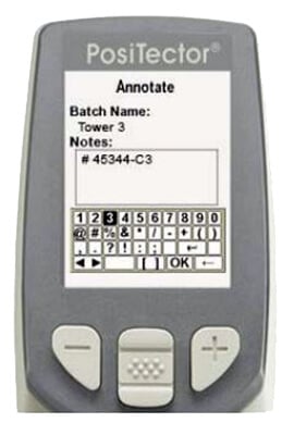
Create meaningful batch names and enter notes directly on the Gage using a familiar onscreen QWERTY keyboard.
Use the Gage's navigation and (-) (+) buttons to enter annotations. Annotations can be synchronized with PosiSoft.net and the PosiTector App and are included in PosiSoft USB Drive reports. |
 |
Sends a statistical summary and individual measurements to the optional Bluetooth wireless printer.
NOTE: To cancel printing, press and hold the (-) and (+) buttons simultaneously.
(appears only if a batch is currently open)
The following chart user selectable display options are available:
 |
None: Default screen shows statistics |
|
Shortcut: When a batch is open, press Up to scroll through the above display options.
NOTES:
- PosiSoft.net and the PosiTector App are used to insert an Image and Notes into a batch.
- Remove the last reading from the current open batch by pressing (-).
- Calibration adjustments cannot be made if any measurements were taken with that setting and stored into a batch.
- If memory is ON while continuous measurements are being taken, only the last value on the display (when the probe is lifted) is stored into memory. Scan Mode stores
ALL measurements into memory. - Each batch can contain a maximum of 10,000 readings.
(Advanced models only)
Displays a summary of all stored batches including the name, probe type, number of readings and type.
| In the following example, Batch 3 (B3) indicates an “F” 6000 coating thickness probe was used to record a total of “6” readings in “PA2” mode. | 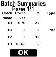 |
| Press both (-)(+) buttons at any time to capture and save an image copy of the current display. The last 10 screen captures are stored in memory and can be accessed when connected to a computer (see PosiSoft USB Drive). | 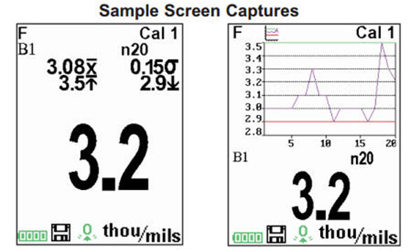 |
![]() Accessing Stored Measurements Data
Accessing Stored Measurements Data ![]()
DeFelsko offers the following free solutions for viewing, analyzing and reporting data:
PosiSoft USB Drive
| Connect the Gage to a PC/Mac using the supplied USB cable. View and print readings and graphs using universal PC/Mac web browsers or file explorers. No software or internet connection required. USB Drive must be selected in the Gage’s “Connect > USB” menu. | 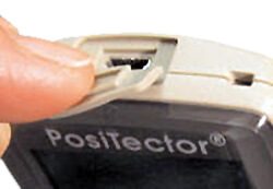 |
Powerful desktop software (PC/Mac) for downloading, viewing, printing and storing measurement data. Includes a customizable, templated PDF Report Generator. No internet connection required.
Web-based application offering secure, centralized storage of measurement data. Access your data from any web-connected device.
(Advanced models only, s/n 784000+)
App for compatible iOS and Android smart devices. Permits users to create, save and share professional PDF reports. Add images and notes using the smart device’s camera and keyboard.
(Advanced models only)
Allows connection to your local wireless network or mobile hot spot. Ideal for using your network's internet connection for synchronizing stored measurements with PosiSoft.net. See www.defelsko.com/wifi |
 |
Enable ![]()
Turns WiFi functionality ON. When selected, the ![]() icon will appear on the display. To deactivate WiFi, uncheck the Enable box.
icon will appear on the display. To deactivate WiFi, uncheck the Enable box.
Connect your smart device/computer to a PosiTector Advanced body wirelessly without the need for a separate network. Wirelessly import readings into PosiSoft Desktop v4.0 Software whenever a WiFi network is not available or out-of-range.
To enable, select Access Point from the Connect > WiFi menu. The Access Point icon ![]() will display in the upper left of the PosiTector display.
will display in the upper left of the PosiTector display.
Securing your Access Point -
To ensure the PosiTector is only accessible to authorized devices, it is important that you enter a passphrase (password) for the Access Point. The default Passphrase is password.
In the Connect > WiFi > Setup menu, select AP Passphrase.
Press ![]() button to display on-screen keyboard. Enter a Passphrase for the Access Point. The Passphrase will be required for all devices connecting to the PosiTector's Access Point.
button to display on-screen keyboard. Enter a Passphrase for the Access Point. The Passphrase will be required for all devices connecting to the PosiTector's Access Point.
The PosiTector is now visible to all WiFi enabled devices. Simply connect your devices WiFi to the new PosiTector Access Point. All PosiTectors are uniquely identified by their respective gage body serial numbers.
AP Channel - Default Channel: 6
For most users the default channel will not have to be altered. If you are experiencing poor connection or are unable to connect, try another channel.
In the Connect > WiFi > Setup menu, select AP Channel
Press the UP center navigation button to highlight the channel. Use the (-) or (+) buttons to change the channel. Press the DOWN navigation button and select OK. Press ![]() the button.
the button.
Networks: With WiFi Enabled the Gage will allow the user to add a new network and will automatically check for available local networks. Available networks detected by the Gage are listed on the screen along with any networks that the Gage has previously been connected to that are not currently within connection range.
Information: Gage displays information about the local WiFi network connection including.
- SSID: the network's name
- State: displays if the Gage is connected to the network or not
- IP Address: the network's IP Address
- Setup: Allows user to setup a WiFi connection
- IP Settings: enter the IP information as follows.
- IP Type (DHCP or Statis), IP Address,
- Gateway, Netmask, DNS1, DNS2
- Server Enable: enables a connection between the network and the Gage
- Gage Name: enter a name for the Gage (up to 14 characters)
- AP Channel: The access point channel corresponding to a frequency range. (Default Channel: 6)
- AP Passphrase: A series of characters, numbers or symbols used to log on to a WiFi network. (Default Passphrase: password)
- WiFi Reset: erases all WiFi settings
When USB Drive is checked ![]() , the PosiTector gage uses a USB mass storage device class which provides users with a simple interface to retrieve stored data in a manner similar to USB flash drives, digital cameras and digital audio players.
, the PosiTector gage uses a USB mass storage device class which provides users with a simple interface to retrieve stored data in a manner similar to USB flash drives, digital cameras and digital audio players.
USB Drive is also required to import stored measurements into PosiSoft Desktop software (pg.24). Once connected, any computer can view measurements stored in memory by navigating a virtual drive labeled "PosiTector” using the included USB cable.
A formatted HTML report is viewed by selecting the "index.html" or “START_HERE.html” file found in the root directory. Optionally, text ".txt" files located in each batch folder provide access to measurement values. Stored datasets and graphs can be viewed or copied using universal PC/Mac web browsers or file explorers.
When your PosiTector is first connected to your Windows PC via a USB cable, an enumeration process is started that installs device drivers without re-booting your computer. You may see several pop-up windows in the taskbar at the bottom right of your screen. Wait for the entire process to be completed before proceeding.
Serial Streaming via USB (Advanced models only, serial numbers 784000 and greater)
Advanced gage bodies have the ability to serial stream live readings from the USB port.
The following document links will help operators use this feature:
PosiTector Advanced USB Serial Streaming Instructions
Retrieving stored screen captures:
The last 10 screen captures stored in memory can be accessed by navigating to the "screen capture" directory within the "PosiTector" virtual drive.
NOTE: When connected, power is supplied through the USB cable. The batteries are not sed and the body will not automatically power down. If rechargeable (NiMH) batteries are installed, the instrument will trickle charge the batteries.
The below WiFi, USB and Bluetooth menus contain a Sync .net Now option. When selected, the Gage immediately synchronizes stored measurement data via its respective communication method (internet connection required).
Alternatively, select Auto Sync .net from within the USB connect menu to automatically synchronize upon connection to a PC. Additional measurements added to memory while connected are synchronized only when the USB cable is disconnected and reconnected, or when the Sync .net Now option is selected.
WiFi connected gages automatically attempt synchronization upon power-up.
NOTE: PosiSoft Desktop is required when using USB or Bluetooth connections to synchronize measurements with PosiSoft.net.
(Advanced models only, serial numbers 784000 and greater) |
When Enabled ![]() , allows communication with a smart device running the PosiTector App via auto-pairing Bluetooth Smart (BLE) wireless technology.
, allows communication with a smart device running the PosiTector App via auto-pairing Bluetooth Smart (BLE) wireless technology.
Select ![]() batches to flag them for synchronization to the PosiTector App. New batches created while Bluetooth Smart is enabled are automatically selected.
batches to flag them for synchronization to the PosiTector App. New batches created while Bluetooth Smart is enabled are automatically selected.
Sync Batches
With Bluetooth Smart enabled, select Sync Batches to transfer selected ![]() batches to the PosiTector App. This is useful when switching between smart devices, as only readings and batches that have yet to be synchronized with any smart device are synchronized automatically.
batches to the PosiTector App. This is useful when switching between smart devices, as only readings and batches that have yet to be synchronized with any smart device are synchronized automatically.
NOTE: If Bluetooth Smart is disabled, data from batches selected in the Sync Batches menu are held in a queue until communication with the PosiTector App is re-established.
Send Batches
Transfers selected ![]() batches to the PosiTector App (useful when switching between devices).
batches to the PosiTector App (useful when switching between devices).
The Send Batches option is visible in the Bluetooth Smart menu when the Gage is connected to a smart device running the PosiTector App.
(Advanced models only)
Allows individual readings to be sent to a computer, printer or compatible device as they are taken using Bluetooth wireless technology. See www.defelsko.com/bluetooth |
Pairing
The instrument and receiving device must be paired before stored or streamed datasets can be transmitted. For pairing instructions, see http://www.defelsko.com/bluetooth
Info
Lists information about your current Bluetooth connection, including the currently paired device and MAC address..
Stream
When checked, the instrument will stream datasets to the paired Bluetooth Device as they are taken. Datasets can be streamed as they are taken to the optional Bluetooth printer or third-party computer software.
Powder Probes
Displays menu options that enable the PosiTector body to communicate with wireless PosiTector PC probes. See http://www.defelsko.com/pc
Determine if a software update is available for your Gage. See www.defelsko.com/update
To perform an update the Gage must be connected to an internet connected PC with PosiSoft Desktop or WiFi network. |
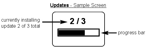 |
WARNING: Ensure that stored measurements are backed up to a PC or PosiSoft.net.
The Gage will perform a Hard Reset after an update. All stored measurements will be erased from memory.
![]() Do Not unplug the Gage during the update operation.
Do Not unplug the Gage during the update operation.
The PosiTector 200 uses an ultrasonic principle to measure coating thickness of most coatings on most substrates. An ultrasonic signal is a very high frequency sound wave. Like the echoes you hear when you shout in a large hall or canyon the PosiTector 200 listens for echoes from acoustic boundaries within your application.
The PosiTector 200 probe emits a high frequency sound pulse that travels into the coating via a coupling gel and reflects from ANY surface that is different in density. Coating thickness readings are obtained by measuring the time taken for the ultrasonic signal to propagate from the probe to the coating/substrate interface and back. The travel time is divided by two and multiplied by the velocity of sound in the coating to obtain the thickness of the coating. The strength of the reflected signal from the coating/substrate interface determines the ability of the Gage to measure the thickness of the coating. Since most applications are not homogeneous the Gage will "hear" many echoes when placed on a coating/substrate. The Gage "hears" ALL reflections within the measurement limits of the Gage and assumes the largest “echo” is the coating/substrate echo (single coating applications only). Adjustable measurement Ranges have been provided for the user to force the Gage to ignore echoes from unwanted boundaries within the sample. Several examples below help to illustrate the use of the Set Range feature for specific applications.
Measuring on coatings with rough surfaces |
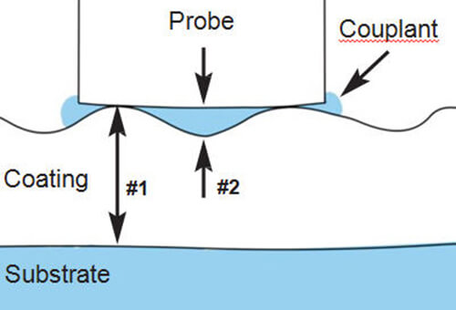 |
When rough coatings are measured, the Gage typically identifies the thickness from the top of the coating peaks down to the substrate (#1). Couplant fills the voids between the probe and the coating (#2) creating an additional interface. If echoes from the couplant/coating interface (#2) are stronger than the coating/substrate interface (#1), an adjustment (increase) of Lo Value may be required for the Gage to display the weaker (#1) echo.
Measurement of dense (hard) coatings
A significant echo occurs at the probe/coating interface. The relative strength of this echo compared to the coating/substrate echo requires that Lo Value be increased.
Measurement of total thickness in multi-layer coating applications
Multiple coating/coating/substrate interfaces may generate several echoes. The user may need to adjust the Gage’s Set Range to ignore echoes from coating/coating interfaces.
Troubleshooting - General
Some common reports received by our Service Department along with possible causes. Most conditions however can be cleared with a Reset.
Gage does not turn on
Make sure the + and - battery terminals are positioned properly and that fresh batteries are being used.
Gage powers up but fails to stay on
Replace batteries with fresh batteries. If problem persists return Gage for service.
Gage readings are much lower than expected
Gage may be measuring surface roughness. Raise the value of Lo Range.
Gage readings are much higher than expected
Gage may be measuring both the coating and substrate. Lower the value of Hi Range.
Gage does not yield accurate or consistent results
See the Set Range and Thickness adjustment sections to ensure the Gage has been optimized for your application. Check the Gage on traceable standards.
Gage displays an error message while attempting probe ZERO
Make sure to hold the probe in the air and ensure the probe is free of couplant and the probe tip area is clean. If problem persists, note the error message and contact our technical support department. |
 |
Gage displays dashed line "----" and emits low-tone buzz while attempting to obtain measurement
This occurs when the Gage is unable to obtain a measurement result. Ensure sufficient couplant (gel) has been applied to the surface of the coating and repeat measurement.
When the Gage is set up for multiple layers, “----” will be displayed for each layer the Gage is unable to obtain a measurement result for. The most common reasons for this is that the individual layers are too acoustically similar or are too thin for the Gage to distinguish between them. Reduce the number of layers the Gage is set up for and repeat measurement.
![]() Power Supply / Battery Indicator
Power Supply / Battery Indicator ![]()
Power Source: 3 AAA alkaline, Lithium or optional Nickel-metal hydride (NiMH) rechargeable batteries. For best battery indicator results, ensure the appropriate Battery Type is selected in the Setup > Battery Type menu.
The battery indicator ![]() displays a full bar with fresh alkaline or fully charged batteries installed. As the batteries weaken, the bar will be reduced. When the battery symbol is low
displays a full bar with fresh alkaline or fully charged batteries installed. As the batteries weaken, the bar will be reduced. When the battery symbol is low ![]() the Gage can still be used, but the batteries should be changed or recharged at the earliest opportunity. The Gage will turn off automatically when batteries are very low, preceded by a Low Battery Warning on the display.
the Gage can still be used, but the batteries should be changed or recharged at the earliest opportunity. The Gage will turn off automatically when batteries are very low, preceded by a Low Battery Warning on the display.
![]() To retain all user settings and stored memory readings, only replace the batteries after the instrument has powered-down. Battery performance decreases at low temperatures.
To retain all user settings and stored memory readings, only replace the batteries after the instrument has powered-down. Battery performance decreases at low temperatures.
Battery performance decreases at low temperatures
Rechargeable Battery Pack
4 - AAA eneloop batteries
The PosiTector can operate on rechargeable batteries and DeFelsko recommends the use of eneloop (NiMH) rechargeables. eneloop batteries combine the advantages of regular rechargeable batteries and disposable (Alkaline) batteries. They discharge very slowly and can be stored for long periods without having self discharge concerns. Eneloop batteries come pre-charged and ready to use immediately. See: www.eneloop.info
AC Power Cable
An optional AC Power Cable Kit is available for continuous operation or battery charging through the PosiTector’s built-in USB port. This kit supplies several alternate power solutions for your battery-operated PosiTector. They allow the gage to operate continuously without the need for batteries.
Use the usb cable alone to connect a PosiTector to your PC's built-in USB port that acts as a continuous power source. Or connect the cable to the included power adaptor which plugs into any AC wall electrical outlet, 110 or 220V.
A selection of electrical plugs is included which are capable of dealing with most country’s outlets.The USB cable provided can also be used for Accessing Stored Measurement Data.
USB Cable
A USB Cable is provided with every PosiTector. The USB cable can also be used for Accessing Stored Measurement Data via the PosiTector USB port or to a connect to a PC's built-in USB port to act as a continuous power source. Replacement USB cables are available.
Couplant
One 4 oz. bottle of Ultrasonic couplant (gel) is provided with every PosiTector 200 probe. Additional 4 oz. bottles are available and sold in a cases of 12.
Bluetooth Printer
This lightweight wireless printer receives data from all PosiTector gages via Bluetooth wireless technology. It is battery-operated and prints readings and statistical summaries.
Nylon Case
Convenient soft shell nylon case for carrying a PosiTector. Case has compartments for Certificates of Calibration, instruction manuals and other accessories.
Protective Lens Shield
One lens shield is included with every PosiTector instrument. Additional package of five (5) thin plastic lens shields are available and ideal for protecting the PosiTector display from paint and overspray.
Coating Thickness Standards
Certified thickness Standards are used to verify the accuracy and operation of coating thickness gages and are an important component in fulfilling both ISO/QS-9000 and in-house quality control requirements. Contracts often specify that coating thickness measurements be taken by gages whose measurement accuracy is traceable to a National Metrology Institute such as NIST or PTB.
Standards are typically purchased as an accessory to coating thickness gages. Many customers find it more practical to verify the accuracy of their own gages in-house, rather than utilize DeFelsko’s calibration services. This is particularly true when many gages are in use and/or when accuracy verification is performed often.
There are 4 types of coating thickness standards available:
Certified Coated Metal Plates are the best solution for verifying the calibration, accuracy and operation of most magnetic, eddy current or ultrasonic coating thickness gages. They fulfill both ISO and in-house quality control requirements. At ±0.43µm (±0.017 mil) Certified Coated Metal Plates are the most accurate solution.
Certified Polystyrene Blocks are for use with C and D probes.
Certified Plastic Shims (foils) provide an economical alternative to coated metal plates. They have a reduced accuracy of ±2 µm (±0.08 mil). A coating thickness Gage measures shim thickness when this shim is placed over a rigid, flat surface.
Non-Certified Plastic Shims (foils) provide a quick operational check of the Gage and they allow the user to perform practice measurements when placed over a rigid, flat surface. A set of 5 shims is included with every PosiTector 200 probe.
This device complies with part 15 of the FCC Rules. Operation is subject to the following two conditions: (1) This device may not cause harmful interference |
 |
and (2) this device must accept any interference received, including interference that may cause undesired operation. |
 |
Before returning the instrument for service.
- Install new or newly recharged batteries in the proper alignment as shown within battery compartment.
- Examine the probe tip for dirt or damage. The probe should move up and down freely.
- Perform a Hard Reset.
- Place a plastic shim onto bare metal (steel or non-ferrous metal, depending upon whether you have an “F” or “N” probe) and attempt a measurement. (See Verification)
- If issue is not resolved, Update (pg. xx) your PosiTector gage body and re-attempt measurements.
IMPORTANT:
If you must return the Gage for service, please fill out and include the Service Form located at www.defelsko.com/support with the Gage. Be sure to also include the probe, your company name, company contact, telephone number and fax number or email address.
![]() Limited Warranty, Sole Remedy and Limitied Liability
Limited Warranty, Sole Remedy and Limitied Liability![]()
DeFelsko's sole warranty, remedy, and liability are the express limited warranty, remedy, and limited liability that are set forth on its website:
www.defelsko.com/terms
© DeFelsko Corporation USA 2017
All Rights Reserved
This manual is copyrighted with all rights reserved and may not be reproduced or transmitted, in whole or part, by any means, without written permission from DeFelsko Corporation.
DeFelsko and PosiTector are trademarks of DeFelsko Corporation registered in the U.S. and in other countries. Other brand or product names are trademarks or registered trademarks of their respective holders.
Every effort has been made to ensure that the information in this manual is accurate. DeFelsko is not responsible for printing or clerical errors.
![]()