Tramex Dec Scanner - Learning
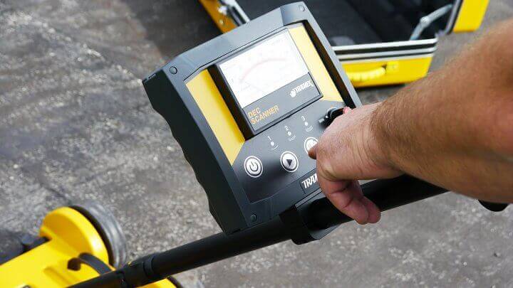
Working with the Dec Scanner |
 |

At Tramex we design quality tools for professionals for use in specialized applications. We believe training is mandatory for using the correct tool to do a great job and we support a large number of excellent training schools around the country to ensure our customers get the most out of our products.
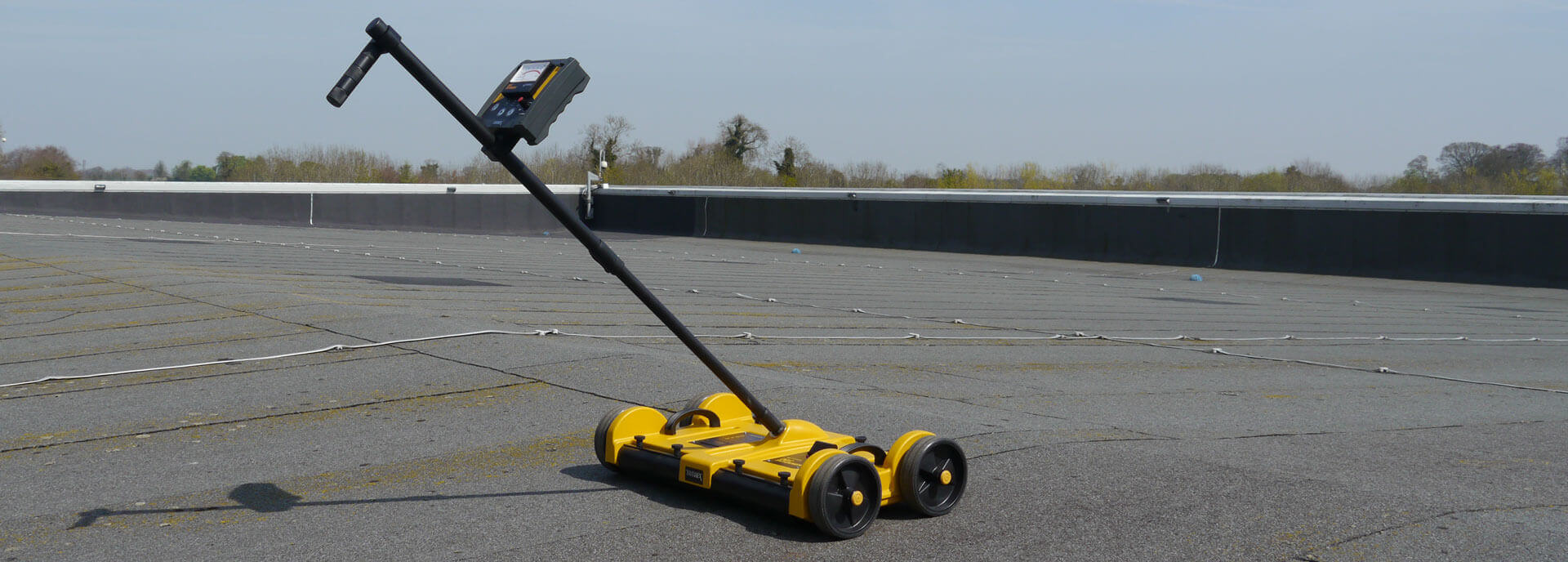
The Dec Scanner is by far the simplest device to use for moisture testing and leak detection of a flat roof, however even a small amount of training can help new users to avoid simple pitfalls.
We will lay out, in these pages, some of the key steps to enable the user to get the best out of this powerful instrument, including setting up and calibrating to a roofing system, developing a methodical approach to inspection and recognising false positives.
|
 |
|
 |
|
 |
|
 |
|
 |
|
 |
|
 |
|
 |
|
 |
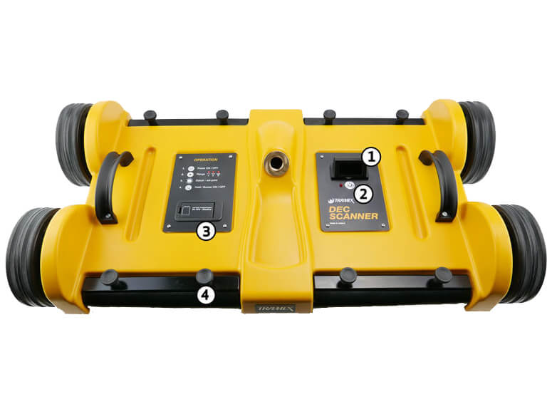
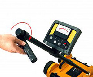
Powering on the instrument
|
|
Notes:
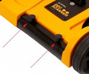
- Low Battery Indication: If the base units LED flashes without the head unit being powered on, this indicates the battery needs replacing and this would be the inverse for the head control unit.
- Audio warning signal may be switched on or off by pressing the pause button twice in succession.
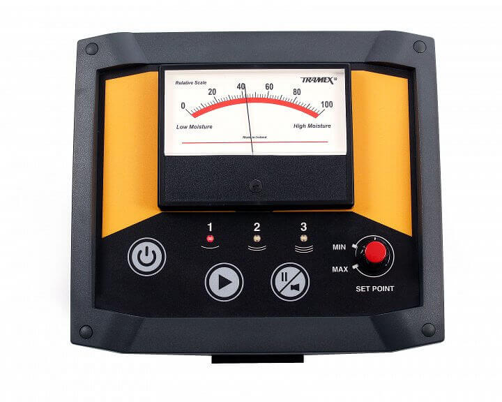
Range 1: Is most suitable for single ply and thin roof coverings with a maximum depth of signal of up to 30-50mm or 1-2 inches (this Range is the least sensitive) Range 2: Is most suitable for 3 and 4 ply (BUR) modified systems and mineral surfaced felts with a maximum depth of signal up to 70-80mm or 1-3 inches (this is the middle Range of sensitivity) Range 3: Is most suitable for thicker roof coverings and thicker layers of insulation, also for gravel and stone surfaced roofing with a maximum depth of 150.0-160.0mm or 1-6 inches (this Range is the most sensitive) |
|
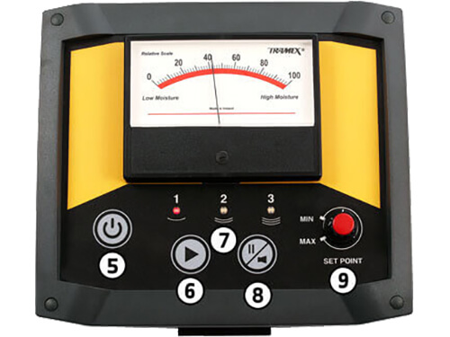
When the unit is powered up and both control panel and base panel are communicating, choose the appropriate Range (as above) with the instrument placed over a known dry area. Adjust the set-point knob, until the needle is just above zero, this will start the signal going into the material under test. If a dry area is not known, position the instrument over a location considered to be dry, adjust the set-point knob until the needle points to mid scale (50). Move the instrument around the roof, following in the direction of lower readings until an area with the lowest readings are found. This should indicate a relative dry area. With the Dec Scanner positioned over this area, adjust the set-point control knob until the needle is just above zero. |
 |
Non-destructive flat roof moisture survey to ASTM D7954
| Obtaining as much information about the roof as possible in advance is invaluable. A set of roof drawings or plans make moisture mapping much easier and a knowledge of the construction will make the job of calibration much faster. |
 |
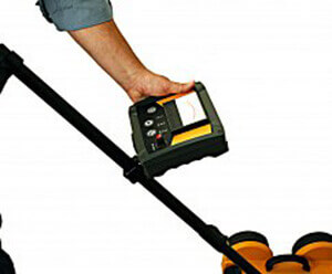
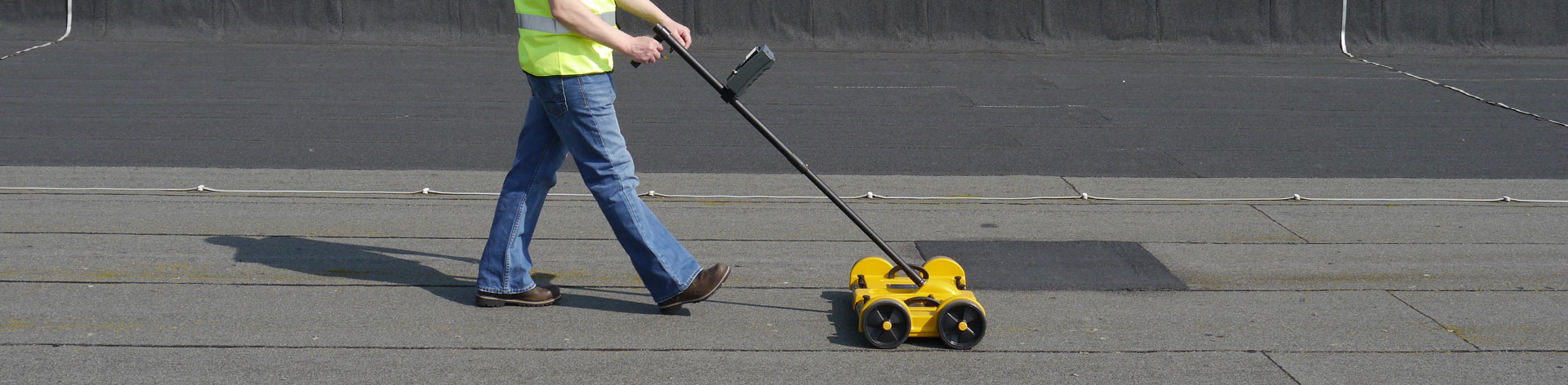
| If a set of drawings or roof plan is not available, prepare a plan and report sheets for each section being surveyed or, better still, use the Tramex Moisture Mapping App. To perform a non-destructive flat roof moisture inspection to ASTM D7954 with the Dec Scanner, first ensure that the surface is free of debris and is dry from rain or dew. Aggregates may be left in place but should be dry and of uniform thickness. Once calibration and range selection is complete, proceed by moving the Dec Scanner along the imaginary gridlines in a continuous, systematic manner. The Dec Scanner is designed to cover the width of an average roll of roofing felt, making it simple to follow a systematic row-by-row methodology. Mark areas of concern onto the roof plan/Tramex Moisture Mapping App as well as directly onto the roof surface if required. Marking the surface directly can be helpful for finding the precise location for core samples later. Areas where the roof has non-uniform composition or thickness, such as areas which have been recovered or seams, should be tested and noted separately as they may provide different results. By continuously checking this way, a complete picture of the moisture condition can be built up quickly. An area of up to 100,000 sqft can be reasonably covered in one day. |
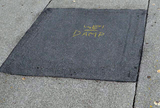 |
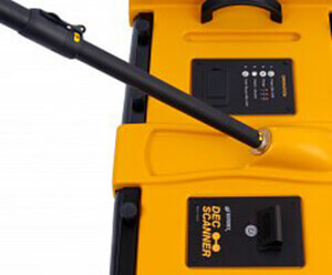
| Selected suspect wet areas should be confirmed by core sampling using gravimetric analysis in accordance with ASTM C1616. It is permitted to check core samples immediately after extraction with a pin-type resistance meter such as the Tramex PTM. An identified area of high moisture may also be checked with extended insulated resistance pins before core sampling, by first puncturing the surface of the roofing membrane with the Tramex Hole Punch and then with the Tramex hand held resistance probe – together with 7" or 15" insulated pins – insert the pins into the insulation for a further relative reading. These readings should be recorded on the report sheets to correlate with gravimetric measurements at the verification stage. | 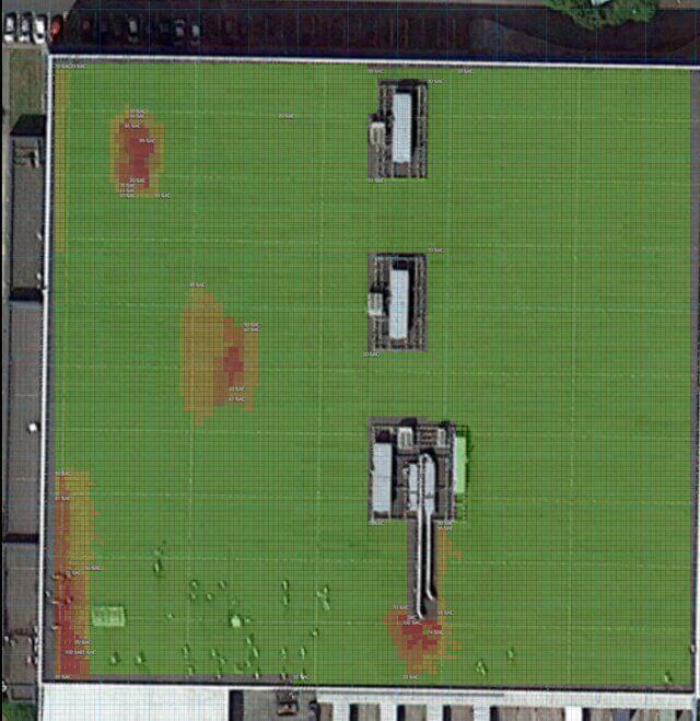 |
Detecting a leak in a flat roof is easy with the Dec Scanner.
- Select the correct range for the type of roof construction in use and adjust the set-point knob until the needle points to mid scale (50).
- Begin in a suspected damp area - such as directly over a leaking area from the ceiling below - and move the instrument around the roof following in the direction of higher readings until full deflection is achieved (100).
When full deflection is achieved, adjust the set-point knob until the needle points back to mid scale (50) and continue as before. - Following the highest reading in this way will normally lead to the entry point of the moisture and thus the leak.
- Areas deemed as damp should be confirmed by core sampling using gravimetric analysis in accordance with ASTM C1616. It is permitted to check core samples immediately after extraction with a pin-type resistance meter such as the Tramex PTM or a resistance probe with the CMEX2.
- An identified area of high moisture may also be checked with extended insulated resistance pins before core sampling, by first puncturing the surface of the roofing membrane with the Tramex Hole Punch and then with the Tramex hand held resistance probe – together with 7" or 15" insulated pins – insert the pins into the insulation for a further relative reading.